
Rooftop Solar Mounting System Selection Guide
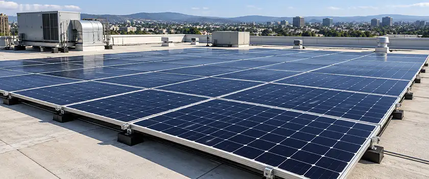
If you have roof photos, a module datasheet and a planned array size, you can usually shortlist mounting hardware, but not make the final choice. The details that settle the choice are often out of sight, in the framing below the roof covering and in the design loads on the original drawings. When they come to light only after the first layout is drawn, attachment counts, ballast weights and even the connection method can still change.
- A rooftop solar mounting system is chosen first to suit the roof covering and the structural capacity beneath it, then sized for site wind, snow and seismic loads under the local building code.
- Ballast is viable only on low-slope roofs whose framing or slab can carry the load at each support. Those point loads can be higher than the average added weight suggests.
- Roof corners, roof edges and exposed array edges see higher wind suction. Attachment spacing or ballast is set zone by zone for the final layout.
- Each penetrating attachment is checked separately for strength and watertightness, and its flashing detail must meet the roofing manufacturer's warranty terms.
Table of Contents
- What Is a Rooftop Solar Mounting System?
- Main Types of Rooftop Solar Mounting Systems
- Mounting Options by Roof Type
- Roof Capacity and Design Loads
- Penetrating vs. Non-Penetrating Mounting and the Roof Warranty
- Choosing Materials for the Site Environment
- Certifications and Engineering Documents
- How to Choose a Rooftop Solar Mounting System Step by Step
- Rooftop Mounting Systems and Layout Support from Mibet
- Frequently Asked Questions
What Is a Rooftop Solar Mounting System?
A rooftop solar mounting system is the set of structural parts between the photovoltaic (PV) module frames and the building. It holds each module at its design position and tilt, and it carries the module weight plus wind, snow and seismic forces into the building structure without compromising the roof's weatherproofing. Installers often just call it rooftop solar racking.
Most systems combine four groups of parts. Roof connections either fasten to the roof or rest on it: flashed L-feet, tile hooks, hanger bolts, seam clamps or ballast bases. Rails or railless mounts carry the modules, mid and end clamps hold the module frames, and bonding clips and grounding lugs connect the metal parts to the equipment grounding path.
Module weight and snow load follow a load path from the clamps through the rails or mounts and roof connections into the structure below: rafters or trusses under shingles and tile, purlins under metal sheets and, on many flat roofs, the roof deck. Wind uplift puts the same path in tension wherever the array is attached. A ballasted array counters it with dead weight.
- PV modules
- Module clamps
- Rails or mounts
- Roof connections
- Rafters, purlins or deck
Main Types of Rooftop Solar Mounting Systems
Rooftop solar mounting systems differ in how they connect to the roof (penetrating, non-penetrating clamps, ballasted or hybrid) and in how the racking above is built (railed, railless or short rails).
Roof Connection Methods
The roof connection determines what resists wind uplift, the net upward force that wind puts on the modules.
| Roof connection | What resists uplift |
|---|---|
| Penetrating (mechanically attached) | Fasteners or anchors fixed into rafters, purlins, the roof deck or the slab |
| Non-penetrating clamps | Clamp grip on the seam or rib, then the roof panel and its clips |
| Ballasted | Weight of ballast, racking and modules |
| Hybrid | Ballast across the array, with anchors added where uplift is highest |
Racking Structure and Tilt
Above the roof connections, three racking designs are common:
- Railed systems run aluminum rails across the attachments and clamp the modules on top. Attachments can sit on the rafters or purlins regardless of where the module edges fall, at the cost of more rail material.
- Railless systems clamp the module frames directly to the attachments, and the frames span from one attachment to the next. They use fewer parts, and the layout has to match both the module dimensions and the rafter or seam spacing.
- Short rails, sometimes called mini rails, are screwed to the rib crests with self-drilling fasteners, and the module edges are clamped to them. They suit trapezoidal metal roofs, where the rib spacing sets the attachment positions.
Tilt and orientation are a separate decision. Modules on pitched roofs, including most metal roofs, usually sit flush, parallel to the roof surface and a few inches above it.
On low-slope roofs, single-tilt rows face the equator on fixed tilt frames or adjustable tilt brackets. Each module in these rows usually produces more energy than one in an east-west layout, but the rows need gaps between them to limit shading. Their tilt angle and row spacing are worked out together with the wind load. East-west arrays place rows back to back at a low tilt and fit more modules on the same roof area.
Mounting Options by Roof Type
Your roof type is the first filter. Each roof covering works with only certain kinds of connection.
| Roof type | Usual mounting approach | Confirm before final selection |
|---|---|---|
| Asphalt shingle | Flashed attachments lagged into rafters, or deck-mounted attachments tested for the sheathing, with rails or railless mounts | Rafter size, spacing and location; sheathing type and condition |
| Clay tile, concrete tile and slate | Tile or slate hooks under the covering, fastened to rafters, with rails | Tile profile, hook clearance, spare tiles |
| Standing seam metal | Non-penetrating seam clamps, with rails or direct module mounting | Seam profile, panel material and gauge, clamp test data |
| Through-fastened trapezoidal or corrugated metal | Hanger bolts, L-feet or short rails fastened through the crests | Purlin spacing, sheet thickness, whether fasteners reach the purlins |
| Concealed-clip ribbed metal (Klip-Lok type) | Clamps that grip the rib without penetrating the sheet | Rib profile and the roof's concealed-clip capacity |
| Low-slope membrane (single-ply TPO, PVC or EPDM, or modified bitumen) | Ballasted, mechanically attached or hybrid | Spare capacity, insulation compressive strength, roofing manufacturer conditions |
| Concrete slab under the roofing | Ballasted, or post-installed anchors through the waterproofing | Slab thickness, tendon locations in post-tensioned slabs, waterproofing detail |
Asphalt Shingle and Tile Roofs
With shingles, the attachment is lagged into a rafter, and its flashing tucks under the shingle course above so that water running down the roof passes over it. A lag screw that misses the rafter is held only by the sheathing. Deck-mounted attachments rely on the sheathing by design, with a screw pattern rated for it.
Tile roofs add a brittle layer between the hook and the framing. Where the hook arm bears directly on the tile below, snow load on the array can press the arm into that tile and crack it. Profiled tile, flat tile and slate each need a tile or slate hook shaped for that covering. The guide to choosing a pitched roof mounting system goes through hook selection for each.
Metal Roofs
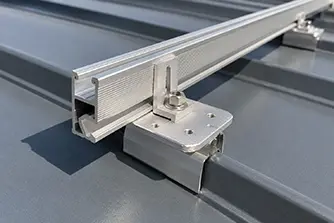
On standing seam roofs, seam clamp capacity varies with seam profile, panel material, gauge and load direction. The rated values are based on test data for that profile, both in uplift and along the seam. From the clamp, the load passes through the panel and its concealed clips into the purlins or deck, so the structural check has to include the panel and clips as well as the clamp.
On through-fastened trapezoidal and corrugated roofs, attachments can be fastened into the purlins or only into the sheets. A purlin-mounted attachment sends load straight into the purlin. A sheet-mounted attachment relies on the sheet thickness, its own fastener pattern and the fasteners holding the sheet to the purlins.
Flat and Low-Slope Roofs
On membrane roofs, a ballasted layout avoids penetrations but adds weight to the insulation and the structure. The insulation needs to carry the bearing pressure under each base without crushing, and a membrane-compatible protection pad between base and membrane limits wear. Friction values hold only for the pad and membrane they were tested on. Swapping the pad after the ballast design is finished can change the sliding resistance the design assumed.
Roof Capacity and Design Loads
The structural check covers the array's own weight and the wind, snow and seismic loads its supports pass into the building.
How Much Weight Does a Rooftop Array Add?
Typical rooftop PV equipment weighs roughly 3 to 6 pounds per square foot (psf), or about 0.14 to 0.29 kPa. That range comes from solar-ready design guidance published by the National Renewable Energy Laboratory (NREL), since renamed the National Laboratory of the Rockies. Ballasted arrays can weigh more, with the ballast sized to the site's wind loads.
An average figure can hide a local overload. For example, an array averaging 4 psf over its footprint delivers its weight as point loads at each attachment or base. A purlin that lines up under a row of supports picks up more than the average implies.
Existing rooftop equipment and any gravel ballast already use part of your roof's capacity, and what remains is the spare capacity available for the array. If your building has no drawings, a structural engineer works out the capacity from a site survey and calculations.
Wind, Snow and Seismic Loads Across the Roof
Airflow separates at the roof edges and corners and produces stronger suction there than over the middle of the roof. Modules at the exposed edges of an array also take more load than those in its interior. Designers turn this into a zone map: closer attachment spacing or more ballast in the corner and edge zones, wider spacing or less ballast in the interior.
- Corner zone
- Edge zone
- Interior zone
- Exposed array edge
In the US, wind loads on rooftop arrays come from the solar provisions in Chapter 29 of ASCE 7-22 or ASCE 7-16, whichever edition the local code adopts. Arrays outside the scope of those provisions, such as taller tilted frames, need a project-specific analysis, often based on wind tunnel testing.
Snow adds gravity load, and drifts against parapets, rooftop equipment or the array itself can concentrate it in one area. Where the array is ballasted, snow and ballast draw on the same spare capacity.
Ballast-only arrays also face a seismic limit. Section 13.6.12 of ASCE 7-22 permits unattached arrays only within limits that include building height and roof slope. An array that cannot meet those limits has to be attached to the roof structure.
Penetrating vs. Non-Penetrating Mounting and the Roof Warranty
Does drilling into the roof void its warranty? Not when the detail suits the roof assembly and meets the roofing manufacturer's conditions. On those terms, penetrating and non-penetrating mounts can both keep a roof watertight and its warranty intact. Where uplift is high or spare capacity is limited, a ballast-only design may not work, and a hybrid or mechanically attached layout takes its place.
A penetrating attachment does two jobs at once. The fastener carries load into the rafter, purlin or slab, and the flashing, sealant or sealing washer keeps water out. The structural engineer checks the first, and the roofing manufacturer's details govern the second. A watertight attachment can still fall short on capacity.
The roof warranty is issued by the roofing manufacturer for a specific roof assembly and is separate from the installer's workmanship warranty. If your roof is under warranty, those terms set the conditions for the solar work. The U.S. Department of Energy's commercial rooftop solar FAQ recommends working with the original roofing manufacturer from design through final inspection. On a commercial project, the coordination usually follows these steps:
- Confirm the current warranty status and terms of the roof.
- Submit the attachment or ballast details to the roofing manufacturer and get written acceptance before work starts.
- Have flashing, or any slip sheets and protection pads required under ballast, installed by a contractor the roofing manufacturer accepts.
- Arrange any post-installation inspection the manufacturer requires and keep the records with the project file.
Choosing Materials for the Site Environment
Material selection turns on each part's structural role, the site's corrosion exposure and contact between dissimilar metals. ISO 9223 classifies atmospheric corrosivity into categories from C1 (very low) to C5 (very high), plus CX for extreme environments. Airborne salt and sulfur dioxide push coastal and industrial sites into the higher categories, and coating thickness and fastener grade are chosen for the category and the intended service life.
| Component | Common material |
|---|---|
| Rails and module clamps | 6000-series aluminum extrusions, mill finish or anodized |
| L-feet and tile hooks | Aluminum, stainless steel or galvanized steel |
| Fasteners | Stainless steel, 304 (A2) or 316 (A4), with 316 common at coastal sites; coated carbon steel for some self-drilling roof screws |
| Tilt frames and ballast trays | Galvanized or zinc-aluminum-magnesium-coated steel, or aluminum |
Galvanic corrosion is a risk wherever two different metals touch and get wet. Small stainless fasteners in aluminum rails are a common pairing, and how fast the joint corrodes depends on the wetted areas of the two metals and on moisture and salt exposure. Runoff from copper roofing can also pit aluminum.
Certifications and Engineering Documents
Documentation requirements vary by market. For the mounting system itself, US permit reviews usually draw on two documents, and each one answers a different question.
| Document | What it establishes | What it does not cover |
|---|---|---|
| UL 2703 listing (US) | Depending on the listing: mechanical strength, bonding and grounding, and fire classification for the racking with specified modules. The fire class has to meet the roof's required class. | Roof attachments and flashing, and the structural design the building code requires |
| Project structural calculations | Loads on the array, attachment spacing or ballast quantities, support reactions; stamped by a licensed engineer where state rules or the local permitting authority require it | The existing roof's capacity, unless the engineer includes it in the scope |
How to Choose a Rooftop Solar Mounting System Step by Step
- Identify the roof covering, profile and remaining service life. Photos, the roof's age and, for metal roofs, a dimensioned profile drawing help decide which connection methods are possible and whether the roof should be replaced first.
- Confirm structural capacity. A structural engineer assesses the remaining capacity using the structural drawings, rafter or purlin spacing, original design loads and existing rooftop loads.
- Set the design loads and corrosivity category. The project location and the applicable code edition determine the basic wind speed, exposure, ground snow load and seismic parameters. Distance to the coast or heavy industry points to the corrosivity category.
- Choose the roof connection method. Pick penetrating, non-penetrating or hybrid based on steps 1 to 3 and the roof warranty terms.
- Settle the racking structure and layout. Lock in the module model at this point, since its size and clamping positions set where the supports go. Leave access to drains, rooftop equipment and any fire-code pathways.
- Assign attachment spacing or ballast by roof zone, then recheck the structural capacity from step 2 against the proposed layout.
- Check the material grades against the corrosivity category. Confirm that the calculations use the locally adopted code and that the listing covers the selected modules and racking.
Rooftop Mounting Systems and Layout Support from Mibet
Mibet supplies rooftop solar mounting systems for tile, slate, metal and flat roofs, including the roof connections, rails and module clamps. Each recommendation starts from the project location and code, the roof covering and profile, the available structural data, the module model, the array size and the site's corrosion exposure.
Send those details with roof photos or drawings, and we will prepare a recommended mounting system and a preliminary array layout, with attachment spacing or ballast set by roof zone. Your structural engineer can then check that layout against the building's capacity before you order.
Frequently Asked Questions
1. Can the same rooftop mounting system be used on residential and commercial roofs?
Partly. The same rails and module clamps are often used on both, but roof connections, design loads, ballast needs and permit documents change with roof type and project size.
2. Do larger solar modules need a different rooftop mounting system?
Usually not, as long as the clamps fit the new frame height. If you switch to larger modules, clamp positions, rail size and attachment spacing still need rechecking for the new layout. The module's own load ratings are established in IEC 61215-2 tests run with the module mounted as its installation manual specifies. Those ratings apply only to the mounting methods the manual lists.
3. What affects the cost of a rooftop solar mounting system?
Installed cost covers the mounting parts, flashing, installation labor and engineering. Attachment count and the corrosion protection grade drive the parts cost, and a ballasted layout adds the blocks and the work of lifting them onto the roof.
4. Can a rooftop solar array be removed and reinstalled when the roof is replaced?
Usually, yes. Modules and rails in good condition can be removed and reinstalled, while the installation manual may call for new clamps with bonding teeth and some new fasteners. Roof attachments and flashing are often replaced along with the new roofing.
5. Can components from different mounting systems be combined?
Components from different mounting systems can be combined only when the mixed assembly has been evaluated as a whole. Matching dimensions do not show that a connection carries the design load or keeps the electrical bonding continuous. Product listings and the system fire classification cover a specific combination of racking components and modules. Swapping in a part from another system takes the assembly outside that evaluation until the new combination is assessed.
Sources used for this article are listed below.
- NREL, Solar-Ready Building Design: A Summary of Technical Considerations, 2017.
- ASCE/SEI 7-22, Minimum Design Loads and Associated Criteria for Buildings and Other Structures.
- U.S. DOE, Frequently Asked Questions (FAQ): Commercial Rooftop Solar, 2015.
- ISO 9223:2012, Corrosivity of atmospheres — Classification, determination and estimation.
- UL 2703, Mounting Systems, Mounting Devices, Clamping/Retention Devices, and Ground Lugs for Use with Flat-Plate Photovoltaic Modules and Panels.
- 2024 International Fire Code, Chapter 12.
- IEC 61215-2:2021, Design qualification and type approval - Part 2: Test procedures.

Tao Chen
Marketing Director & IT Director · MIBET ENERGY
MIBET is a global designer and manufacturer of solar mounting systems. With over 10 years of professional experience, Tao Chen regularly contributes articles to our blog on structural design, installation, and maintenance, offering valuable guidance for navigating the complexities of solar projects.