
Aluminum Solar Panel Mid and End Clamps
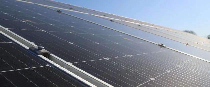
Clamp selection usually starts with one figure from the module datasheet: frame height. Match it, and the clamps seat cleanly on the frame. Two other variables decide whether the snow and wind ratings printed on that same datasheet still apply: where along the frame each clamp lands, and how much of the frame it grips. Under IEC 61215-1, module documentation states the design load separately for each mounting method. A clamp can fit the frame and still land outside the clamping zone listed in the module manual. In that position, the module is no longer mounted the way it was tested for its load rating.
Aluminum solar panel mid and end clamps hold framed modules to the mounting rails. Mid clamps sit between adjacent modules and end clamps hold the outer frame at each row end, giving each module four clamping points on a standard two-rail layout. Most clamps are anodized 6000-series aluminum extrusions, such as 6005-T5, with stainless steel bolts. Installed correctly, each clamp matches the frame height and contact length, locks into the rail channel, lands inside the module manual's clamping zones, and is torqued to specification.
Table of Contents
- Solar Panel Mid Clamps vs End Clamps
- Which Clamp Size Fits Your Module Frame?
- Aluminum Alloy, Finish, and Stainless Fasteners
- Where Is the Best Place to Clamp a Solar Panel?
- How Many Mid and End Clamps Do You Need?
- Installing Mid and End Clamps Step by Step
- Get Aluminum Mid and End Clamps Matched to Your Modules
- Frequently Asked Questions
Solar Panel Mid Clamps vs End Clamps
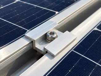
A mid clamp holds two modules at the joint between them. An end clamp holds a single module at each end of a row. Both are top-down clamps that press the frame onto the rail. In a typical pre-assembled clamp, a bolt passes through the clamp body and threads into a channel nut held in the slot along the top of the rail.
Mid clamps, sometimes listed as middle clamps, have two symmetrical clamping surfaces, so a single bolt holds the edges of both frames. Because the frames on both sides are the same height, the clamp stays level as the bolt pulls it down.
Solar panel end clamps grip only one frame. With the frame on one side of the bolt and nothing on the other, the load on an end clamp is off-center. As the bolt is tightened, and again when wind lifts the module, the clamp tends to tip outward and slip off the frame edge. Most end clamps counter this with a body that stands on the rail beside the frame. That body holds the clamping jaw at frame height and lets the frame top and the rail share the bolt load.
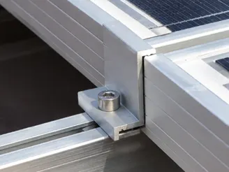
The uplift load path runs from the glass through the frame, clamps, and bolts into the rails and the structure below. On a roof, the load continues into attachments such as metal roof clamps, L-feet, or tile roof hooks. Ground-mount, carport, and floating arrays carry it into their own support structures. In a clamped array, the clamps are the only parts holding each module down against uplift.
Because the two clamps do different jobs, most bills of materials list mid and end clamps as separate line items. The exception is a universal mid/end design, where one part covers both positions.
| Feature | Mid clamp | End clamp |
|---|---|---|
| Position | Between two adjacent modules | Outer edge of the first and last module in each row |
| Clamping surfaces | Two, symmetrical | One, with a body that stands on the rail beside the frame |
| Load behavior | Shared by two frames, one on each side of the bolt | Offset from the bolt, so the clamp tends to tip outward |
| Rail requirement | Fits wherever two modules meet | Needs rail length past the last module |
Which Clamp Size Fits Your Module Frame?
Solar panel mounting clamps have to match three things: your module's frame height, the contact length set in the module manual, and the rail channel. Frame heights of 30 mm and 35 mm are common on current modules, and other heights are still in production.
Frame Height and Clamp Type
End clamps are more sensitive to height because the body rests on the rail and sets the jaw at a fixed height:
- If the clamp body is taller than the frame, the jaw hovers above the frame top, and tightening tilts it down onto the frame edge.
- If the body is shorter than the frame, the jaw stays below the frame top and cannot reach over it.
Height matters less for mid clamps, which pull down onto the frames anywhere within the bolt's working range. That range ends where the bolt bottoms out in the rail channel on a lower frame, or runs short of thread engagement in the nut on a taller one.
Clamp designs differ in how they handle frame height and row position:
| Clamp design | How it works | Where it fits best |
|---|---|---|
| Fixed-height | One clamp size per frame height, such as separate 30 mm and 35 mm end clamps | Projects built around a single module model |
| Height-adjustable | One clamp covers a range of frame heights, commonly starting near 30 mm and reaching 40 to 50 mm, depending on the design | Contractors working with several module models, and module replacements |
| Universal mid/end | The same part works as a mid or end clamp after rotating or reconfiguring the body | Simplified stock, since one part covers both positions |
Checking Contact Length and Rail Fit
Two more dimensions are fixed at the factory and belong on your pre-order check: clamp length and jaw reach. Module manuals can set a minimum clamp length, because a longer clamp spreads the clamping force along more of the frame. Trina Solar's Vertex Series user manual, for example, recommends an aluminum clamp at least 50 mm long and 4 mm thick for the modules it covers. It also requires the jaw to overlap the frame's top surface by 8 to 12 mm, and the clamp must neither touch the front glass nor shade the module.
The channel nut also has to match the width and lip profile of the rail channel so it locks in place when the bolt turns. If the nut is too narrow for the channel, it spins with the bolt and the clamp never tightens.
Aluminum Alloy, Finish, and Stainless Fasteners
A standard clamp pairs an aluminum body with a stainless steel bolt. In 6005-T5, 6005 names the alloy and T5 the temper. A T5 profile is cooled straight from the extrusion press and then artificially aged to raise its strength. Anodizing converts the outer surface of the aluminum into a hard oxide layer that slows corrosion and resists scuffing during handling. Clamps come in clear or black anodized finishes to match silver or black module frames. Either way, the oxide layer does the protective work.
Stainless steel is the usual bolt material because it resists rust and keeps its threads in good condition outdoors. Does that stainless bolt corrode the aluminum around it? Slowly, yes. The two metals form a galvanic couple, and corrosion starts once an electrolyte such as rainwater or condensation bridges them. Aluminum is the more active metal of the pair and the one that corrodes. Two features keep the rate low in a typical clamp:
- Area ratio. A small stainless part against a much larger aluminum area keeps the attack slow, though corrosion can still form right around the joint.
- Insulation. The anodized layer separates the two metals over much of the contact surface.
For most inland roofs and ground mounts, anodized clamps with 304 stainless fasteners are the common specification. Sites in higher corrosivity categories, including many coastal locations, usually move up to 316 stainless fasteners and a thicker anodic coating.
Where Is the Best Place to Clamp a Solar Panel?
The best place is inside the clamping zones the module manufacturer lists for your mounting method. The highest-rated zones usually lie along the long sides of the frame, within a set distance range from each corner.
Clamping Zones in the Module Manual
Module installation manuals pair each mounting method with its own allowable loads. Each method spells out the number of clamps, the side of the frame they grip, the direction the rails run, and, in some manuals, a minimum clamp length.
Datasheet figures such as 5,400 Pa downforce (front) and 2,400 Pa uplift (back) therefore belong to a specific mounting method. Trina Solar's Vertex manual rates the same NEG18R modules differently depending on which side the four clamps grip:
| Four clamps on | Downforce, front (Pa) | Uplift, back (Pa) |
|---|---|---|
| Long side, rails crossing the long frames | 5,400 | 2,400 |
| Short side | 1,300 | 1,000 |
Source: Trina Solar Vertex Series user manual (UM-M-0002 Ver. PP7).
All of these are test loads. Dividing by the manual's 1.5 safety factor gives the design loads your structural engineer checks against the site's wind and snow loads under the local code.
How Rail Direction Sets the Clamping Edge
The rails decide which edge the clamps grip, not portrait or landscape orientation alone. Portrait modules on horizontal rails are clamped on the long side, and so are landscape modules on rails that run up the slope. Landscape modules on horizontal rails are clamped on the short side. If the short-side rating comes in below your site loads, rails running up the slope move the clamps to the long sides. The rail spans and roof attachments then need rechecking for that direction.
The clamps mark the module's support points under wind or snow pressure. Where they sit sets the span between supports and the overhang beyond them, which in turn decides how far the frame and glass deflect. Outside the zone, the published rating no longer applies, and stress can concentrate in the glass and cells. Over time, cell microcracks may form and reduce output. The figure below marks the zones on a single module and shows how a row's rails and clamps line up with them. Treat it as illustrative, since each module's manual sets the actual zones.
- Long-side clamping zone
- Short side, rated separately
- Outside listed zones
- End clamp
- Mid clamp
- A Corner-to-clamp distance, within the range in the module manual
How Many Mid and End Clamps Do You Need?
A two-rail layout holds each module at four points, two per rail. Adjacent modules share mid clamps, so a row of N modules on two rails follows a fixed pattern:
Mid clamps = 2 × (N - 1)
End clamps = 4
For example, a 10-module row needs 18 mid clamps and 4 end clamps.
Each time your array breaks, whether around a roof vent or between separate sections, the new row segment needs four more end clamps on a two-rail layout. A layout split into many short rows therefore uses more end clamps per module than one continuous row.
Installing Mid and End Clamps Step by Step
Installation Sequence and Torque
Install the clamps one row at a time, working from one end to the other. The steps below assume top-down clamps with channel nuts, on rails that are already fixed and aligned.
- Check the layout first. Confirm that rail positions fall inside the clamping zones and that the clamp size matches the frame height of the delivered modules.
- Start with an end clamp. Place the first module so the rail extends past the frame by at least the overhang the clamp instructions call for. Slide or drop the end clamp into the rail channel, seat its body on the rail against the frame, and hold it while tightening so it does not turn with the bolt.
- Add a mid clamp. Seat it in the channel against the first module and slide the next module tight against the clamp body.
- Tighten to the specified torque. Check that the channel nut has turned fully under the channel lips, then tighten to the value given in the clamp's installation instructions.
- Repeat to the end of the row. Finish with an end clamp on the last module, installed the same way as the first.
- Check the row. Spot-check torque on a sample of clamps and confirm the modules sit flat and in line.
Torque matters because it sets bolt preload, the tension in the bolt that becomes the clamping force on the frame. Where the clamp instructions allow a power driver, your crew can run the bolts down with it and finish tightening with a calibrated torque wrench.
Mistakes That Loosen or Damage Clamps
- Channel nut not fully seated. A nut that jams against the channel walls before turning fully under the lips can still give a full torque reading. Under uplift, it may pull out of the channel.
- Torque outside the specified value. Excess preload can dent the top of the frame or strip the channel nut threads, and a dented frame no longer gives the clamp a flat bearing surface. Low preload can let wind vibration and daily thermal cycles gradually work the bolt loose.
- End clamp too close to the rail end. With less rail past the frame than specified, the end clamp body and nut may not seat fully on the rail. Once the clamp loosens, it can slide off the open end.
Get Aluminum Mid and End Clamps Matched to Your Modules
Mibet supplies aluminum solar panel mid and end clamps in height-adjustable and universal mid/end designs. Each clamp arrives pre-assembled with its bolt and channel nut, leaving no loose parts to sort on the roof. You can order the clamps together with rails for Mibet's roof, ground, carport, and floating mounting systems.
Send us your module datasheet, installation manual, rail profile, and array layout to get a clamp specification and quantity list for your project.
Frequently Asked Questions
1. Can a mid clamp be used as an end clamp?
A mid clamp can serve as an end clamp only if it is a universal mid/end design or is fitted with the end-support part specified for it. A standard mid clamp has two symmetrical clamping surfaces meant to press on two frames. At the end of a row, one surface has no frame beneath it, so the clamp tips as the bolt tightens and grips the remaining frame only at its edge. The reconfigured clamp or added part then bears on the rail beside the frame, like a dedicated end clamp.
2. Are solar panel clamps universal?
Solar panel clamps are not universal across every module and rail system. Compatibility depends on frame height, the required contact length, and the fit between the channel nut and the rail. A channel nut that locks in one rail can spin in another. "Universal" in a product name usually means one of two things: the clamp works in both mid and end positions, or it covers a stated range of frame heights.
3. Do mid and end clamps ground solar panels?
Standard anodized clamps do not, because the anodized layer is an electrical insulator. Bonding links the module frames and rails into one continuous conductive path, and the equipment grounding conductor ties that path into the electrical system's grounding. Two kinds of hardware usually provide that path:
- clamps or clips with stainless steel teeth that cut through the anodizing, or
- separate grounding clips and lugs installed at the module's grounding points.
In North America, bonding clamps are typically evaluated to UL 2703 as part of a specific racking system with listed modules. The clamp's bonding rating holds only within that combination. The bonding method on a project follows the local electrical code, such as Article 690 of the US National Electrical Code or AS/NZS 5033 in Australia and New Zealand.
4. How much gap do mid clamps leave between panels?
On clamps with a center spacer, the gap equals the spacer width. It also needs to meet the minimum spacing between modules set in the module manual. Because spacer widths vary between designs, the gap belongs in the rail length calculation. For a row of N modules, start with N times the length of the module edge that runs along the row. Then add N - 1 gaps and the specified overhang at each end.
5. Are aluminum clamps suitable for coastal installations?
Yes. Anodized aluminum clamps with stainless steel fasteners are used on coastal sites, and the site's corrosion exposure decides the exact specification. Under ISO 9223, atmospheric corrosivity runs from C1 to CX, with examples ranging from C3 for coastal areas with low chloride deposition to C5 for generic coastal areas. A coastal location alone does not fix the category. Project specifications for the higher categories often move to 316 stainless steel fasteners and a thicker anodic coating. Rail channels, where salt and water collect, also go on the regular inspection list.
Sources used for this article are listed below.
- IEC 61215-1:2021, Terrestrial photovoltaic (PV) modules - Design qualification and type approval - Part 1: Test requirements.
- Trina Solar User Manual Vertex Series Modules, UM-M-0002/Ver. PP7.
- Euro Inox, Stainless Steel in Contact with Other Metallic Materials, 2009.
- Review of Failures of Photovoltaic Modules, IEA-PVPS T13-01:2014.
- UL 2703, Mounting Systems, Mounting Devices, Clamping/Retention Devices, and Ground Lugs for Use with Flat-Plate Photovoltaic Modules and Panels.
- ISO 9223:2012, Corrosion of metals and alloys — Corrosivity of atmospheres — Classification, determination and estimation.

Tao Chen
Marketing Director & IT Director · MIBET ENERGY
MIBET is a global designer and manufacturer of solar mounting systems. With over 10 years of professional experience, Tao Chen regularly contributes articles to our blog on structural design, installation, and maintenance, offering valuable guidance for navigating the complexities of solar projects.