Types of Solar Mounting Structures: Roof, Ground and Floating
The mid and end clamps that hold photovoltaic (PV) modules change relatively little from one project to the next. The surface under the array varies far more. A roof's load allowance is already fixed by the building, though a structural engineer still has to check it. Soil and open water give no such head start: nobody can say how the structure will be held in place until they have been surveyed. Because the surface sets the limits for the rest of the design, it decides the structure family, and with it the site investigation the project pays for first.
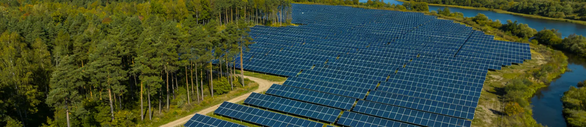
Solar mounting structures fall into three main types: roof-mounted structures held by roof attachments or ballast, ground-mounted structures carried on foundations in or on the ground, and floating structures supported by buoyant floats and held in position by mooring lines. Which type fits a project depends on the surface available and its measured condition: the roof's structural capacity, the soil and groundwater, or the water depth and range of water levels. Pole mounts, solar trackers, carports and agrivoltaic structures belong to the ground-mounted family as subtypes.
Table of Contents
- Main Types and Subtypes of Solar Mounting Structures
- Roof Mounting Structures by Roof Type
- Fixed, Tracking and Elevated Ground Mounting Systems
- How Floating Solar Mounting Systems Work
- Roof vs. Ground vs. Floating Mounting Structures
- Which Materials Are Used in Solar Mounting Structures?
- How to Choose a Mounting Structure for Your Site
- Plan Your Roof, Ground or Floating Project with Mibet
- Frequently Asked Questions
Main Types and Subtypes of Solar Mounting Structures
Some published lists count five types, separating top-of-pole mounts, side-of-pole mounts and tracking systems from standard ground mounts. All three still pass their loads into foundations in the ground, just as fixed-tilt racking does. This article treats them as ground-mounted subtypes, along with carports and agrivoltaic structures that leave room for parking or farming. Wall-mounted, balcony and building-integrated photovoltaic (BIPV) systems fall outside the three families covered here.
| Family | Common subtypes | What holds it in place | Key design checks |
|---|---|---|---|
| Roof-mounted | Standing seam and trapezoidal metal roof systems, tile and shingle roof systems, ballasted and attached flat roof systems | Clamps, hooks or anchors fixed to the roof, or ballast weight and friction | Spare capacity of the roof structure, and wind uplift at roof edges and corners |
| Ground-mounted | Fixed-tilt racking, pole mounts, single-axis and dual-axis trackers, carports, agrivoltaic structures | Driven piles, ground screws, concrete foundations or ballast blocks | Soil and rock conditions, foundation capacity and wind on the array |
| Floating | Pure-float platforms, floats carrying a metal frame, membrane or mat platforms | Buoyancy of the floats, plus mooring lines to bank, bottom or pile anchors | Buoyancy, mooring loads, water-level range and wave exposure |
Roof Mounting Structures by Roof Type
A roof-mounted array relies on two parts of the building. The covering dictates how the structure attaches. The framing underneath limits how much extra weight the roof can carry and how much uplift each support can resist. If your roof covering is near the end of its life, re-roofing before installation avoids having to remove and reinstall the array later.
Standing Seam and Trapezoidal Metal Roofs
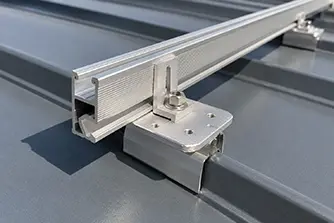
On a standing seam roof, seam clamps grip the raised seams, leaving the roof sheets free of fastener holes. Klip-Lok, a common concealed-fix profile, has non-penetrating clips with jaws shaped to its ribs. Each clamp has to match its roof profile, because holding capacity measured on one profile does not transfer to another.
Trapezoidal and corrugated sheet roofs need attachments that go through the sheet. Aluminum mini-rails are screwed to the ribs, or hanger bolts pass into the purlins and carry an L-foot for the rails. Purlin-fixed hanger bolts give the load a direct path into the building frame. Sheet-fixed mini-rails depend on the sheet and its existing fasteners, and sheet thickness and screw pull-out capacity set the attachment spacing.
Tile and Shingle Roofs
Tile hooks are fixed to the rafters and pass between the overlapping tiles to carry the rails, with the hook arm clear of the tile below. Asphalt shingle roofs, common on North American homes, use L-feet lagged into the rafters through a flashing that sheds water around each penetration. Arrays on both roof types are usually flush-mounted, parallel to the slope.
Ballasted, Attached and Hybrid Flat Roof Systems
On flat roofs with only a slight slope, the array can be held down by weight alone. In a ballasted system, concrete blocks sit in trays on the racking: their weight resists uplift, and friction against the roof surface resists sliding. The trade-off is permanent dead load from the modules, racking and ballast. That weight bears on the roof as a concentrated load through the protection pad under each base.
Mechanically attached systems anchor the racking to the deck or framing and add far less weight, but each anchor needs a flashed penetration. Hybrid layouts combine the two. Ballast typically holds down the interior of the array, and anchors go in near the edges and corners, where airflow separates from the roof and uplift peaks.
Fixed, Tracking and Elevated Ground Mounting Systems
Whatever the subtype, a geotechnical investigation of the soil, rock and groundwater narrows down the foundation types the site can use. Driven piles and ground screws suit most soils. Rock or cobbles may call for pre-drilling or concrete. On ground that must not be penetrated, such as a capped landfill, ballast blocks take over.
Fixed-Tilt Ground Racking and Pole Mounts
Fixed-tilt racking holds the modules at a set angle on single-post or dual-post frames. Latitude gives the starting tilt, but a steeper array catches more wind and casts a longer shadow on the row behind. Rows end up farther apart, and less capacity fits on your site. For that reason, tilt angle, wind load and row spacing are worked out together.
Pole mounts carry a small array on a steel pole, either on top of it or clamped to its side, and suit off-grid and compact installations. With the whole array on one support, that single foundation takes the full overturning moment from wind.
Single-Axis and Dual-Axis Trackers
Horizontal single-axis trackers, which turn rows about a north-south axis, are the standard choice for large plants in many markets. Dual-axis trackers remain a niche option. In the United States, Berkeley Lab's 2025 data update found that 99% of new utility-scale PV projects in 2024 used single-axis tracking.
Then why use fixed-tilt racking at all? Because trackers only pay off on the right site. Each row rotates on a straight torque tube carried by closely aligned piles, and steep or uneven ground makes that alignment hard to hold. Drives, bearings and controllers need regular maintenance, and the rows rely on a stow mode that turns them to a protective angle in high wind. How much extra energy single-axis tracking delivers depends mainly on the share of direct sunlight at the site.
Carports and Agrivoltaic Structures
A solar carport has to clear vehicles and keep its columns out of stalls and drive aisles. Single-column cantilever frames carry the canopy on one row of columns, and two-column frames suit heavier snow or wind loads.
Agrivoltaic structures make room for crops, livestock or farm machinery. Germany's pre-standard DIN SPEC 91434 classifies them by where the farming takes place. Category I covers overhead systems that leave at least 2.1 m (about 7 ft) of clearance for farming underneath, and Category II covers interspace systems with farming between the rows.
Height also adds load on carports and overhead systems. Wind pressure increases with height above the ground, and the resulting force acts through a longer lever arm. Both effects raise the moment at the column base and the load on the foundation. On a carport, that moment is one of the main inputs to solar carport frame design.
How Floating Solar Mounting Systems Work
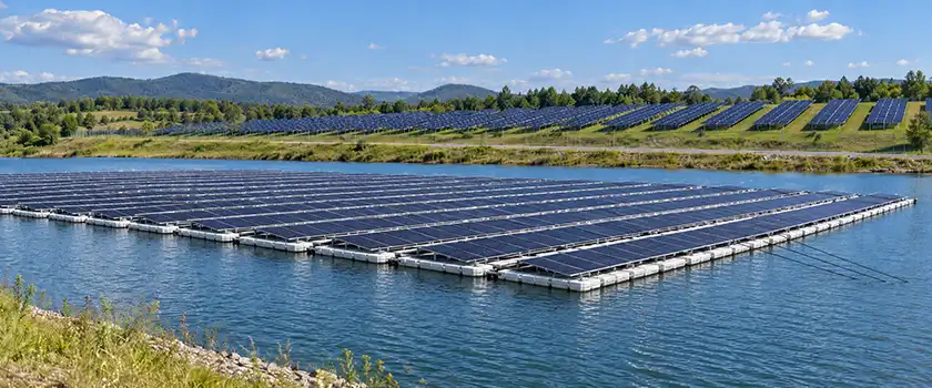
In most floating systems, the modules sit on floats molded from high-density polyethylene (HDPE), either directly or on a metal frame carried by the floats. The floats are joined into one platform, often called a float island, and mooring lines tie it to anchors. The mooring lets the island move within set limits as the water level changes and wind and waves push on it.
Float Platform Designs
The three common designs differ mainly in what carries the modules, the same distinction an IEA PVPS review of floating PV plants uses to group them.
| Platform design | How the modules are carried | Design considerations |
|---|---|---|
| Pure-float | Modules are clamped to main floats shaped to set the tilt | The floats and the pins joining them carry all structural load. UV resistance and joint strength govern the design |
| Floats carrying a metal frame | A frame of steel, aluminum or both sits on floats or pontoons, and the modules mount to the frame | The frame leaves room for airflow beneath the modules, and its coatings and connections stay exposed to moisture over the water |
| Membrane or mat | Modules rest on a flexible membrane or mat held by a floating structure | Less common. The membrane follows the water surface, and the water beneath it cools the modules |
Mooring and Anchoring
Bank anchoring ties the island to anchors on the shore and suits islands close to the bank. Bottom anchoring relies on weights or embedded anchors on the bed, and pile anchoring on piles driven into it. Large plants often combine methods around the perimeter.
Mooring design starts from the range of water levels, because the distance between each anchor and the island changes as the water moves. As the water falls, lines to bottom anchors slacken and the island can drift and rotate. When a slack line snaps taut, it sends a shock load into the connections. As the water rises, the same lines tighten; if they are too short, they pull down on the perimeter floats. Line length and layout, often with elastic mooring elements, keep the island on station across the full range. For sheltered inland and near-shore water, DNV's 2026 standard DNV-ST-E309 sets out how the resulting mooring loads are derived and checked.
Roof vs. Ground vs. Floating Mounting Structures
The three families differ most in where the engineering work and cost concentrate: the existing building on a roof, foundations and earthworks on land, and floats and mooring on water.
| Factor | Roof-mounted | Ground-mounted | Floating |
|---|---|---|---|
| Typical project scale | Residential to large commercial, limited by roof area | Small off-grid systems to utility scale | Small ponds to utility-scale reservoirs |
| Energy yield factors | Roof orientation and shading from parapets or rooftop equipment | Tracking where direct sunlight is strong, plus terrain and row spacing | Cooler modules where air moves underneath, plus low tilt, wave motion and bird droppings |
| Permitting and environmental review | Building permit and structural review of the existing building | Land use, environmental, grading and drainage approvals | Water use, ecological review and consent from the water body's operator |
| Main cost drivers | Roof condition, attachment count or ballast, lifting and access | Foundations, earthworks and, where used, trackers | Floats, mooring and anchoring, water-based installation and cabling |
When you compare quotes, check the scope of supply first. A racking-only price covers less than one that includes foundations, ballast or mooring and their installation. Either way, a quote is only as reliable as the site data behind it.
Which Materials Are Used in Solar Mounting Structures?
Solar mounting structures are built mostly from aluminum and coated steel and joined with stainless or galvanized steel fasteners. Floating systems add HDPE floats.
| Material | Typical use | What to check |
|---|---|---|
| Aluminum extrusions 6005-T5, 6063-T6 | Rails, clamps, roof systems, some carport and ground frames, floating module supports | Deflection, since aluminum's elastic modulus is about one-third that of steel |
| Hot-dip galvanized steel ASTM A123, ISO 1461 | Piles, posts, beams, carport columns, floating frames | Coating thickness matched to the corrosivity category and design life |
| Zinc-aluminum-magnesium (Zn-Al-Mg) coated steel ASTM A1046, EN 10346 | Roll-formed purlins, rails and support legs | Coating class and cut-edge exposure for the site's corrosivity category |
| Stainless steel fasteners Types 304, 316 | Bolts, nuts and washers at clamps and connections | Type 316 near the coast, and contact with other metals in wet conditions |
Corrosion protection is specified for the site's atmospheric corrosivity category. ISO 9223 classifies exposure from C1 (very low) to CX (extreme), and sites with heavy salt deposition near the shore fall in the upper categories. Under the standard, zinc in a C5 environment corrodes several times faster in its first year than in C3. For buried pile sections, engineers use the soil resistivity and pH from the geotechnical report.
How to Choose a Mounting Structure for Your Site
- Collect the site data each family depends on. Roofs need a structural assessment and a check of the covering's age and condition. Land needs a topographic survey and a geotechnical investigation. Water needs bathymetry (a survey of the depth and shape of the bed), historical water levels and wind and wave records, plus bed soil data where bottom or pile anchors are planned.
- Decide the array layout. Tilt and orientation, tracking, clearance for parking or farming, and walkway access on water each rule some subtypes in and others out.
- Set the design loads under the governing code. Wind, snow and seismic loads for that layout come from the loading code your jurisdiction has adopted, such as ASCE 7 in the United States or the Eurocodes in Europe. The edition in force determines which provisions apply. ASCE 7-22, for instance, introduced wind provisions for fixed-tilt ground-mounted arrays in Section 29.4.5. Floating arrays must also account for wave and current loads.
- Match materials to exposure and design life. The corrosivity category and design life set the coating, the alloy and the fastener material. Writing them into your specification before bids go out lets every supplier price to the same corrosion requirements.
Plan Your Roof, Ground or Floating Project with Mibet
Mibet designs and manufactures solar mounting structures for roof, ground and floating projects, sized to each site's conditions and loading code. The roof mounting systems include metal roof clamps and L-feet, tile roof hooks and ballasted flat roof systems. Ground mounting systems cover fixed-tilt racking, single-axis trackers, carports and agrivoltaic structures, and floating PV systems combine HDPE floats with aluminum and corrosion-protected steel framing.
Send us the project location, planned capacity, module datasheet, site type and any roof drawings, geotechnical report or water-level records you have. You will receive a preliminary layout, a recommended mounting system and a budget quote.
Frequently Asked Questions
1. What is the difference between a solar mounting structure, a mounting system and solar racking?
The three terms generally describe the same equipment. Where a distinction is drawn, mounting structure means the load-bearing frame and mounting system means the complete kit, including clamps, attachments and fasteners. Racking is the usual North American term for either. Solar panel mounting brackets are usually individual components such as tilt legs, hooks or L-feet, although some suppliers use the word for the whole structure.
2. Do solar mounting structures need certification?
Requirements vary by market and mounting type. In the United States, UL 2703 covers rooftop and freestanding PV racking, including bonding and grounding, mechanical strength and fire classification. Solar trackers are also evaluated to UL 3703. In the European Union, load-bearing steel and aluminum components generally need CE marking to EN 1090-1. A listing supports, but does not replace, the structural design required by the local building code.
3. How long do solar mounting structures last?
A mounting structure is normally specified to last at least as long as the modules it carries, and crystalline silicon modules commonly come with 25- to 30-year performance warranties. For fixed steel and aluminum structures, reaching that life depends mainly on corrosion control: a coating matched to the site's corrosivity category, protected cut edges and compatible fasteners.
4. Will a non-penetrating solar mount affect my roof warranty?
Yes, a non-penetrating mount can still affect your roof warranty. Besides penetrations, warranty terms cover added load, materials in contact with the roof covering, drainage paths and installation methods. The roofing manufacturer may need to approve the work first.
Sources used for this article are listed below.
- Berkeley Lab, U.S. Utility-Scale Solar, 2025 Data Update.
- DIN SPEC 91434:2021-05, Agri-photovoltaic systems - Requirements for primary agricultural use.
- Floating Photovoltaic Power Plants: A Review of Energy Yield, Reliability, and Maintenance, IEA-PVPS T13-31:2025.
- DNV-ST-E309, Station keeping of floating solar photovoltaic systems, 2026.
- ISO 9223:2012, Corrosion of metals and alloys — Corrosivity of atmospheres — Classification, determination and estimation.
- ASCE/SEI 7-22, Minimum Design Loads and Associated Criteria for Buildings and Other Structures.
- UL 2703, Mounting Systems, Mounting Devices, Clamping/Retention Devices, and Ground Lugs for Use with Flat-Plate Photovoltaic Modules and Panels.
- DIN EN 1090-1:2012-02, Execution of steel structures and aluminium structures - Part 1: Requirements for conformity assessment of structural components; German version EN 1090-1:2009+A1:2011.
Tao Chen
Marketing Director & IT Director · MIBET ENERGY
MIBET is a global designer and manufacturer of solar mounting systems. With over 10 years of professional experience, Tao Chen regularly contributes articles to our blog on structural design, installation, and maintenance, offering valuable guidance for navigating the complexities of solar projects.