Solar Panel Angle Brackets: Wind Load and Row Spacing
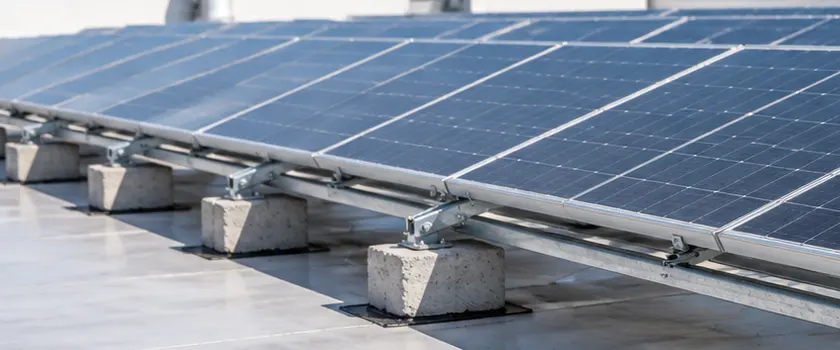
In solar, we usually talk about tilt as an energy question. For the mounting structure, it is also a question of geometry and load. When you select solar panel angle brackets, the tilt setting changes the height of the module's high edge, the space needed between rows, and the wind loads on its supports. Those effects matter most on commercial roofs and multi-row ground arrays, where usable area and structural capacity can both limit the design.
Solar panel angle brackets set the module tilt, and tilt affects both row spacing and wind load. A steeper setting raises the module's high edge. Its shadow gets longer, and the next row needs more distance to meet the same shading criterion. Pressure coefficients and overturning moments tend to rise too, because the steeper module presents more of its face to the wind and the resulting force acts higher above its supports. In your project, the size of these effects comes down to module size, wind direction, array position, neighboring rows, and the design code that applies.
Table of Contents
- What Changes When You Adjust the Bracket Angle
- How Solar Panel Tilt Affects Wind Load
- Why a Steeper Tilt Needs Wider Row Spacing
- Row Spacing and Wind Shielding Between Rows
- Selecting Tilt Means Balancing Energy, Area, and Structure
- What to Confirm Before You Choose a Bracket Angle
- Custom Adjustable Tilt Design and Structural Checks
- Frequently Asked Questions
What Changes When You Adjust the Bracket Angle
Adjusting the bracket angle raises or lowers the module's high edge and changes its horizontal depth. Row layout and structural design both start from these two dimensions, and on a level surface each follows from simple trigonometry:
vertical rise = sloped row length × sin(tilt angle)
horizontal depth = sloped row length × cos(tilt angle)
The sloped row length runs from the low edge to the high edge. It is the module's long side in portrait and its short side in landscape, or the full stacked length, gaps included, when two or more modules sit one above the other up the slope. Take the dimension from the module datasheet or drawing.
Module Length and Tilt Set the Vertical Rise
As a simple example, take a 2.0 m sloped length. At 30°, it rises 1.0 m and takes up about 1.73 m of horizontal depth. At 15°, the rise drops to about 0.52 m and the depth grows to about 1.93 m.
A steeper tilt trades horizontal depth for height. Both effects follow from that extra height. It lengthens the shadow toward the next row, and it lifts the module higher above its supports.
Roof Pitch Changes the Final Module Tilt
For example, a 15° bracket on a 10° roof can end up at 25° or at 5°. Tilt the module the same way as the roof slope and the angles add. Tilt it against the slope and they subtract. Across the slope, both the final tilt and the azimuth change, so the geometry needs a three-dimensional check. The resulting tilt and azimuth are what the shading and wind calculations use.
All of this assumes you know how the bracket angle is quoted. Depending on the product, the adjustment range is measured from the mounting surface or from horizontal, and the drawing shows which. On a low-slope roof, the bracket angle and the final tilt are close but rarely identical, since most of these roofs still have a small fall for drainage.
How Solar Panel Tilt Affects Wind Load
A steeper tilt tends to increase the wind load on the module and its supports. In a 2021 study, researchers tested a single ground-mounted panel in a wind tunnel and reported the results in the Journal of Wind Engineering and Industrial Aerodynamics. Net pressure coefficients were higher at 45° than at 25°. Uplift, drag, and overturning each peaked under a different wind direction. In an installed array, the final load also depends on wind direction, the module's location, neighboring rows, and the surface below.
Tilt, Lever Arms, and Support Forces
Wind can press a tilted module down onto its supports or lift it off them, depending on which way it blows. Because the face is inclined, part of that force also pushes sideways on the frame.
Raise the tilt and the resultant moves up with the module. Its horizontal component now acts on a longer lever arm about the support base, so the overturning moment generally rises. The pressure distribution changes too, and with it the split between front and rear reactions.
Those forces travel through the clamps, rails, and tilt legs into the roof attachments or foundation.
- Module surface
- Module clamps
- Rails
- Tilt legs
- Roof attachment or foundation
A ballasted array resists them with dead weight instead. How much each part takes depends on the frame geometry and the connection layout.
On many adjustable brackets, the rear leg extends at steeper settings. In compression, a longer leg has a lower buckling capacity, as long as the section and end restraints stay the same. Under uplift, the same leg and its connections can go into tension. The rear-leg check therefore runs at every setting.
Wind Direction and Array Position
Two modules at the same tilt can carry quite different wind loads. Near roof edges and corners, the airflow separates from the roof surface, and modules there see higher local pressures. In a ground-mounted array, the leading row takes the approaching wind head-on, while the rows behind it sit partly in the turbulent air it sheds. Building height, parapets, and terrain shift the pattern further.
Codes with PV-specific provisions account for these edge and leading-row effects in their pressure coefficients. In the United States, ASCE/SEI 7-22 has separate provisions for tilted arrays on flat roofs and on gable or hip roofs sloped less than 7°, for modules mounted parallel to the roof, and for ground-mounted fixed-tilt arrays, each with its own geometric limits. The ground-mount provisions are new to the 2022 edition. Which edition is in force for a given project depends on the building code adopted locally.
Other markets have their own standards, including the wind-action standards EN 1991-1-4 in Europe and AS/NZS 1170.2 in Australia and New Zealand, and JIS C 8955, which covers loads on PV array structures in Japan. Whichever code applies, a tilt-up array on a roof steeper than 7°, or a layout outside the method's limits, needs another design basis that the code accepts, such as wind-tunnel data for that specific system.
Bracket datasheets usually quote a rated wind speed. So what does that number actually cover? Only the tilt, module size, support spacing, and exposure it was calculated for. Check those before you compare two products.
The code behind the number matters as well. ASCE 7 uses a 3-second gust, and the Eurocode basic wind velocity is a 10-minute mean, with different reference conditions and return periods behind each. Equal m/s figures do not describe the same wind.
Check Every Planned Tilt Setting
Some adjustable solar panel brackets are set once during installation, which lets one kit cover several roof angles or design tilts. Others are made to be reset through the seasons. If you plan to adjust the tilt during the year, the manufacturer's approved settings and adjustment procedure define which settings the array can use. Either way, each setting in use is its own design case.
The steepest setting usually produces the highest wind pressure and the longest lever arm, which makes it the first case to check for overturning, attachment uplift, and rear-leg forces. It may not govern every member, though. Each load type has its own critical wind direction, and a connection that controls the design at one setting can have spare capacity at another. For a seasonally adjustable array, the structural review should cover every setting the array will actually use, or show by calculation which settings govern.
Shading follows the season. Check each setting against the sun positions for the months it is in use. A schedule that raises the tilt in winter puts the steepest setting and the lowest sun together, and that pairing often sets the row spacing.
Why a Steeper Tilt Needs Wider Row Spacing
Under the same sun position, a steeper row casts a longer shadow, and the next row has to be set farther back to stay clear of it. How far back depends on the module dimensions, array orientation, the sun position used for design, site slope, and how much inter-row shading the project will accept.
How Shadow Length Sets Row Pitch
Two measurements sit behind the term row spacing, and the industry uses it loosely for both. Clear spacing is the horizontal gap between the high edge of one row and the low edge of the next. Row pitch is measured from a point on one row to the same point on the next, so it adds the row's own horizontal depth to the clear spacing. The lower the sun, the longer the shadow, and solar azimuth sets its direction relative to the rows.
Back to the 2.0 m example, now on level ground with both rows at the same height and the sun 30° above the horizon, facing the rows straight on. At 15° tilt, the 0.52 m rise needs about 0.90 m of clear spacing to keep its shadow off the next row, which puts the row pitch at about 2.83 m. At 30°, the 1.0 m rise needs about 1.73 m, and the pitch grows to about 3.46 m. That is roughly 22% more, for the same shading criterion.
Some layouts use a shade-free window on the winter solstice, such as 10:00 to 14:00 or 9:00 to 15:00 solar time. A wider window keeps more of the winter day free of inter-row shading but takes more row pitch. Other projects accept limited shading and set the spacing by annual energy yield. A rule of thumb that sets a fixed number of meters between rows for a 30° array holds only for one combination of location, module size, orientation, and shading window. Change any of them and the number changes too.
Row Pitch, GCR, and Installed Capacity
Ground coverage ratio (GCR) is the sloped length of a row divided by the row pitch. In the same example, going from 15° to 30° drops GCR from about 0.71 to about 0.58. If your roof or site boundary is fixed and the module layout stays the same, a lower GCR means fewer rows and less installed capacity.
GCR matters for wind design too. The ASCE 7-22 ground-mount method covers only ratios between 0.2 and 0.6, among other limits, so the tighter 15° layout would need another design basis.
Row Spacing and Wind Shielding Between Rows
Spreading rows apart reduces inter-row shading, but it also changes the wind shielding between rows. The turbulent air behind a row, known as its wake, partly shields the row downstream, so interior rows usually carry lower wind loads than the leading row.
The effect shows up row by row in wind-tunnel tests on ground-mounted arrays, published in the Journal of Fluids and Structures in 2014. Force and moment coefficients fell most sharply at the second row, with little further reduction beyond the fourth. When the researchers widened the spacing, the coefficients climbed.
Change the spacing after the wind design is done, and the pressure coefficients used may no longer apply. Where the design method accounts for row shielding, wider spacing can raise uplift and overturning on the downstream rows. Any ballast, attachment, or foundation checks based on the tighter layout then need updating for your revised array.
Selecting Tilt Means Balancing Energy, Area, and Structure
When tilt is still a design variable, project teams can run the energy model for several tilt and spacing combinations and test each option against the available area and the structural limits.
Energy per Kilowatt vs. Energy per Site
Tilt changes how much sunlight reaches a module and when. On an equator-facing array, steeper settings shift output toward the low-sun winter months. On a site with a fixed boundary, the layout has to weigh two measures: energy per installed kilowatt (kWh/kWp) and total energy from the available roof or land. They pull in different directions.
Raises kWh/kWp up to a point, but fits fewer modules on the site.
Fits more modules and can raise total site energy, even though each kilowatt produces a little less.
A 2018 design example in Solar Power World modeled the same rooftop in Miami and Seattle. With modules tilted at the site's latitude and rows spaced to stay shade-free from 10:00 to 14:00 on the winter solstice, the roof could fit a 545 kWdc array in Miami and only 240 kWdc in Seattle. At a 10° to 15° tilt, the gap between the two cities narrowed to about 10%. Location and layout rules changed together in that comparison, but it still shows how strongly tilt and the shading window can change the capacity that fits on a fixed roof.
Site and Structural Constraints Narrow the Practical Tilt Range
On some projects, available area sets the limit. On others, the roof or the foundation does.
- Ballasted arrays. A steeper setting often needs more ballast to resist uplift and sliding, and that extra dead load has to fit within the roof's reserve capacity.
- Mechanically attached arrays. Attachment forces can rise with tilt, and the layout may need more attachments or closer spacing.
- Ground-mounted arrays. Any increase reaches the posts or piles as uplift and overturning, which can mean deeper embedment or larger foundations.
When one of these limits controls the design, a slightly lower tilt with more rows can produce more total energy than the angle with the best kWh/kWp.
What to Confirm Before You Choose a Bracket Angle
A bracket's stated adjustment range tells you which angles it can reach. The table below lists the inputs that decide whether one of those angles works for your project, and where each one usually comes from.
| Project Input | What It Affects | Typical Source |
|---|---|---|
| Module dimensions, frame height, and orientation | Vertical rise, shadow length, clamp selection, support layout | Module datasheet and drawing |
| Planned tilt settings | Support geometry and the settings that need structural and shading checks | Energy model and operating plan |
| Roof pitch or ground slope | Final module tilt, clearances, and row geometry | Roof drawings or site survey |
| Array layout and available area | Row pitch, array density, and wind shielding between rows | Layout drawings |
| Site wind design basis (code, design wind speed, exposure) | Loads on rails, legs, clamps, and connections | Local building code and the project engineer |
| Roof capacity, attachment, foundation, or ballast limits | How loads enter the supporting structure | Roof structural assessment or geotechnical data |
| Maintenance access | Clearances between rows and around equipment | O&M plan |
Where snow or seismic loads apply, the relevant tilt settings are checked under the load combinations the governing code requires. If that code allows a slope reduction in snow load, the reduction depends on the panel slope and on snow being able to slide off. The flattest setting on an adjustable array can therefore govern the snow check.
Custom Adjustable Tilt Design and Structural Checks
Mibet designs adjustable tilt mounting systems project by project for roof-attached, ballasted, and ground-mounted arrays, including brackets that can be reset through the seasons. Our engineers size the supports and connections for your planned tilt settings and check the load path from the modules to the roof or foundation at each one.
Send us your module model, proposed tilt settings, site location, roof or layout drawings, and shading criterion. If the wind and snow design criteria are already set, include them as well.
Frequently Asked Questions
1. Does a steeper solar panel angle always increase wind load?
Not always. Pressure coefficients and overturning moments generally rise with tilt, but wind direction, array position, and support geometry decide which setting governs a particular member. On an adjustable array, a flatter setting can govern other checks, such as snow.
2. Does wider row spacing reduce wind load?
Usually not for the rows behind the leading row. Each row partly shields the one downstream, and wind-tunnel tests on ground-mounted arrays found that force and moment coefficients rose as row spacing increased. The size of the effect varies with tilt, wind direction, and row position.
3. Can the same angle bracket be used with different solar panel sizes?
It can, as long as the new module fits the bracket's rail length, clamp range, and support spacing, and the clamps can sit within the module's approved clamping zones. The structural check needs to be rerun for the new size, because, all else equal, a larger module puts more tributary area on each clamp and rail.
Here is a list of the sources used to create this article.
- An experimental and numerical study of wind effects on a ground-mounted solar panel at different panel tilt angles and wind directions. Journal of Wind Engineering and Industrial Aerodynamics, 2021.
- ASCE/SEI 7-22, Minimum Design Loads and Associated Criteria for Buildings and Other Structures.
- EN 1991-1-4, Eurocode 1 – Wind Actions.
- AS/NZS 1170.2:2021, Wind Actions.
- JIS C 8955:2017, 太陽電池アレイ用支持物の設計用荷重算出方法.
- Reconciling Heliostat and Solar Panel Wind Loads To Develop a Reduced-Order Model for Heliostat Wind Loads. NREL/TP-5000-96375, 2025.
- Influence of spacing parameters on the wind loading of solar array. Journal of Fluids and Structures, 2014.
- The new rules for latitude and solar system design. Solar Power World, 2018.

Tao Chen
Marketing Director & IT Director · MIBET ENERGY
MIBET is a global designer and manufacturer of solar mounting systems. With over 10 years of professional experience, Tao Chen regularly contributes articles to our blog on structural design, installation, and maintenance, offering valuable guidance for navigating the complexities of solar projects.