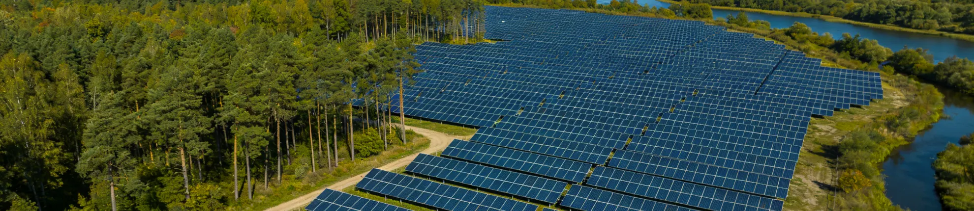
What Determines Ground Mount Solar Structure Design?
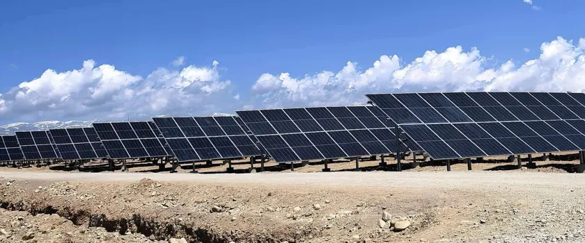
Two ground-mounted PV projects can use the same module at the same nominal tilt and still need different support structures once the site conditions are known. Wind exposure and ground levels change post spacing, member sections and foundation reactions. Soil chemistry and atmospheric exposure determine the corrosion protection. Project capacity tells you almost nothing about any of it. For a fixed-tilt ground mount, the design starts from the module and table geometry, then develops around site actions, ground conditions and how the structure will be installed.
Four inputs dominate ground mount solar structure design: the module and table geometry, the site wind and snow criteria, the ground conditions, and the foundation interface. Materials, corrosion exposure and construction tolerances then shape the detailing. From those, engineers establish member sizes, spans, spacing, connections and foundation reactions, then check the completed configuration against the project criteria and applicable standards.
Table of Contents
- Module and Array Geometry Set the Starting Point
- Wind Governs the Structural Demand on Most Australian Sites
- Two Kinds of Site Data Shape the Ground Interface
- The Load Path Links Modules, Members and Foundations
- Specifying Materials for the Structure and the Site
- Which Australian Standards Apply to a Ground Mount Structure?
- What Information Should an EPC Provide Before Structure Design Begins?
- From Project Inputs to an Installable Ground Mount Structure
- Frequently Asked Questions
Module and Array Geometry Set the Starting Point
A PV table is a single structural unit carrying a fixed group of modules. Its width, length, tilt and height define the geometry used in every later calculation. Two tables with the same module count place different demands on the structure if their module dimensions or arrangement differ.
What the Structural Engineer Needs from the Module Data Sheet
Module wattage belongs to the electrical design. The mechanical interface depends on a different set of numbers: module length, width, mass, frame height and the mounting positions the module manufacturer permits. Frame height decides which clamp fits, since the jaw has to match it.
The clamping zone is the approved part of the module frame where clamps or supporting members may be positioned. A module's mechanical load rating comes from testing in one specific mounting arrangement, so a clamp placed outside that zone takes the module beyond the configuration the rating covers. Moving it takes written confirmation from the module manufacturer.
Alter the module dimensions or the allowable clamp positions and the rails or purlins move with them. A late module substitution therefore reaches the structural drawings and the bill of materials, even when the electrical design stays broadly the same.
Table Configuration Affects Spans and Load Distribution
Module orientation and grouping give the table its physical shape. Portrait and landscape arrangements produce different support geometry. Module rows within the table, modules per table and the chosen support arrangement all feed into table dimensions, rail spans, beam positions and post spacing.
Table size by itself does not specify a structural section. Where the module-support members sit, where the posts land and how load travels between them decide the section.
| Array Input | What It Changes in the Structure |
|---|---|
| Module dimensions | Clamp positions and rail or purlin spacing |
| Module orientation | Table layout and member arrangement |
| Modules per table | Table dimensions and how load distributes to the posts |
| Tilt angle | Projected area facing the wind and net pressure on the table |
| Ground clearance | Post height, the lever arm at the base and access underneath |
Setting Tilt and Ground Clearance
Tilt usually follows from energy yield, row spacing and site layout. It also changes the surface the wind sees and the relative heights of the supporting members. In higher wind regions, project teams sometimes trade a degree or two of tilt for lower wind actions, a yield decision as much as a structural one.
Ground clearance determines post height, and post height acts as a lever arm. The same lateral wind force produces a larger bending moment at the base as the table sits higher.
M = F x h. The force and the lever arm both come from the project's own design wind actions and table geometry.
Tilt and ground clearance both need confirming before the support arrangement is finalised. Energy modelling settles the preferred array geometry, and structural engineering then works out how that geometry can be carried on the actual site.
Wind Governs the Structural Demand on Most Australian Sites
On fixed-tilt projects, wind is the action that sizes most of the structure. Snow applies only where the site location and design criteria call for it. In Australia that means alpine areas. The modules and the mounting members make up the permanent actions, and the combinations come from AS/NZS 1170.0.
Wind Acts Across the Whole PV Table
In the wind tunnel tests behind the Australian provisions, interior rows carried the same uplift as the front row.
That work, published as Wind Loads on Ground Mounted Solar Panels by the JCU Cyclone Testing Station, found negligible shielding from upwind arrays in the suction case. Across every array tested, upwind and downwind alike, the top row of panels at the leading edge reached aerodynamic shape factors near -2.5, and the leading top corner panel roughly -3.5. Downward pressure does drop on the interior rows. Uplift does not.
Site wind speed combines the regional gust speed with multipliers for wind direction, climate change, terrain category, shielding and topography. Most solar farm sites fall in Terrain Category 2, open terrain with scattered obstructions. Shielding usually contributes nothing on these sites, because the standard allows only upwind buildings to provide it and excludes trees and vegetation.
A wind rating on a quotation carries the region, terrain category, table height and annual probability of exceedance that produced it. Ask for those alongside the headline figure.
Two mounting configurations priced against the same wind speed can carry quite different design actions once those values are filled in.
Where the Ground-Mount Clause Applies
Australian projects work to AS/NZS 1170.2:2021, Structural design actions, Part 2: Wind actions. Appendix B of that standard is normative and covers freestanding walls, hoardings, canopies and solar panels. Clause B.6.2 deals with arrays mounted on the ground, and it entered the standard in the 2021 edition.
The tabulated coefficients apply where the ground-mounted array meets all five conditions:
- Array tilt up to 30 degrees
- Array depth between two and five times the reference height
- Array length at least twice the array depth
- Row spacing 3.5 to 10 times the reference height
- Underside clearance at least 0.2 times the reference height
The tabulated coefficients stop at those limits. An array beyond them needs its wind actions established on another basis.
Two amendments have followed, in May 2023 and June 2024. Neither touched B.6.2, though the second revised neighbouring clauses in B.6, so your engineer should work from the current consolidated text.
Two Kinds of Site Data Shape the Ground Interface
Ground mount design draws on two different sets of site information. Site topography describes the surface geometry and the ground levels. Geotechnical data describes what lies below.
Site Topography Changes Post Lengths and Table Stepping
On level ground, repeated tables follow a consistent elevation. Undulating or sloping sites call for different post lengths, stepped tables or more adjustment at the connections.
Slope in the tilt direction, north to south on most Australian sites, adds to or subtracts from the tilt relative to horizontal, and shifts the front and rear clearances. Slope along the table axis is normally absorbed by varying the post lengths or stepping the table.
Past a certain gradient the posts run out of adjustment, and the tables have to be stepped or earthworks brought in. Where that point sits changes with the structural arrangement, the foundation type and the table geometry.
For more on ground conditions, earthworks and project suitability, see Pros and Cons of Ground-Mount Solar Racking Systems.
Geotechnical Data Sets the Foundation Design Basis
Structural analysis gives the forces and moments arriving at the base of the supporting members. The foundation then has to move those reactions out into the surrounding ground.
The geotechnical data underpins the checks on uplift resistance, lateral resistance, bearing, settlement, embedment and installation feasibility. Soil resistivity, pH, chloride and sulfate figures decide how buried steel is protected, and whether that testing falls inside the investigation scope is worth confirming before the brief goes out. On larger sites the soil profile varies across the array, so one foundation assumption may not suit every zone.
Driven piles, ground screws, concrete foundations and ballast each suit different site conditions. Foundation selection is a separate design task, following the structural reactions, the ground conditions and the installation method. Foundation Types for Ground-Mount Solar Systems compares the options in detail.
The Load Path Links Modules, Members and Foundations
Tracing the forces through the structure turns module geometry, site actions and ground conditions into member-level demands.
The load path runs from the PV module, through the supporting members and connections, into the foundation and the ground.
Loads Move from the Module to the Ground
For a typical fixed-tilt table:
- PV module
- Module clamp
- Rail or purlin
- Main beam or rafter
- Post
- Foundation
- Soil
Terminology varies between mounting systems. Some product families call the module-support member a rail, others a purlin. Both describe members that carry the modules and pass their loads to the primary structure.
Every member and connection along this route has a structural job. Spare capacity in a main beam does not compensate for an undersized connection or an unsuitable foundation interface further along the path.
For a member of unchanged section carrying a uniformly distributed load, the bending moment rises with the square of the span and the deflection with the fourth power. A small increase in post spacing therefore raises the beam demand by much more than the spacing change suggests.
Where Connections Fit in the Load Path
Ground mount structures repeat the same connections many times over: module clamps, rail connectors, brackets, splice plates, bolts and other fasteners. Each one transfers force between adjacent members, and its geometry decides the assembly sequence, the alignment and the amount of adjustment available on site.
Slotted holes and adjustable brackets accommodate defined construction tolerances. They also cut the bearing area and allow a little slip before the bolt takes up, so these connections are either designed as bearing type with that slip accounted for, or they rely on a defined bolt preload. After positioning and final tightening, the connection still carries the full design load.
Specifying Materials for the Structure and the Site
Structural checks establish the capacity required from the mounting frame. The material specification has to suit the environment those members work in over the design working life.
Ground mount structures commonly use hot-rolled structural steel, cold-formed steel sections, aluminium or a combination of these, with fasteners and coatings to match.
Steel and Aluminium Behave Differently in the Frame
Aluminium is about a third as stiff as steel, with an elastic modulus near 70 GPa against 200 GPa. A member of the same section and span deflects around three times as much, so aluminium rails end up deeper than their steel equivalents, or supported at closer spacing.
Cold-formed sections are rolled or pressed from steel sheet or strip, and in thin walls local and distortional buckling govern in a way they rarely do in a heavier hot-rolled section.
AS/NZS 4600 covers members cold-formed from steel sheet, strip or plate, and AS 4100 covers hot-rolled steelwork. That split carries down to connection level: Clause 5.3 of AS/NZS 4600 applies to bolted connections where the connected part is thinner than 3 mm, and AS 4100 takes those at 3 mm and above. Aluminium members follow AS/NZS 1664.
Matching Corrosion Protection to the Exposure Category
How much protection a steel section needs changes from one part of Australia to the next, and AS 4312 assigns each site an exposure category.
The categories run from C1 in dry sheltered inland conditions up to CX in the most aggressive coastal and industrial exposures. AS/NZS 2312.2 uses the same definitions and ties them to expected coating life. On that basis, a hot dip galvanised coating around 85 micrometres thick gives an estimated 20 to 40 years to first maintenance in a C4 environment. The same coating in a higher category reaches first maintenance sooner.
AS/NZS 4680:2025 covers the coating itself and the test methods. That revision moved the last of the design content out of 4680, so durability is now handled entirely in 2312.2.
A single post crosses two corrosion environments.
AS 4312 sets the atmospheric corrosivity category for the site, and the coating thickness follows from that category.
The atmospheric categories stop at the ground surface. Soil resistivity, pH and chloride content govern instead, and those figures come from the geotechnical report.
Which Australian Standards Apply to a Ground Mount Structure?
Together, the project inputs covered so far form the design basis the structural checks run against. Which standards apply depends on the structure, the materials, the project scope and the approval pathway.
The references below track the topics this article covers. They are not a complete compliance checklist.
| Design Topic | Australian Reference | What It Decides |
|---|---|---|
| Load combinations | AS/NZS 1170.0:2002 | How permanent, wind and snow actions combine for the limit states being checked |
| Wind actions | AS/NZS 1170.2:2021, incorporating Amendments 1 and 2 | Site wind speed, aerodynamic shape factors and the geometric limits of the ground-mount clause |
| Snow actions | AS/NZS 1170.3:2003 | Ground snow load and the shape coefficients used where snow governs |
| Hot-rolled steelwork | AS 4100:2020, incorporating Amendment 1 | Member capacity, stability and connection design for hot-rolled sections |
| Cold-formed steelwork | AS/NZS 4600:2018 | Local and distortional buckling, direct strength method, connections in parts under 3 mm |
| Aluminium members | AS/NZS 1664.1 and 1664.2:1997 (REC:2020) | Limit state design (Part 1) or allowable stress design (Part 2) for aluminium sections |
| Corrosivity category | AS 4312:2019 | The C1 to CX exposure category that applies to the site |
| Galvanising design and durability | AS/NZS 2312.2:2014 | Coating life against corrosivity category, venting, drainage and steel chemistry |
| Galvanised coating specification | AS/NZS 4680:2025 | Coating thickness, appearance, adhesion and the test methods |
Some states require the structural design to be certified by a registered engineer, and the approval pathway defines who signs and what they need to see.
Product certification covers narrower ground. A certification or an existing calculation package applies within a defined design envelope, meaning the conditions and configurations that assessment actually examined. A project that falls outside that envelope needs engineering assessment against its own design inputs.
What Information Should an EPC Provide Before Structure Design Begins?
A mounting engineer needs more than a megawatt figure and a site name. Before the structure can be defined, the EPC contractor needs to provide project geometry, design actions, ground conditions and exposure data.
| Project Input | What It Tells the Structure Designer |
|---|---|
| Project location | Wind region and atmospheric corrosivity category |
| Design working life and importance level | Annual probability of exceedance behind the design wind speed |
| Wind and snow design criteria | Regional wind speed, terrain category, site multipliers and snow condition |
| Site layout and topographic survey | Ground levels, table stepping and earthworks |
| Geotechnical information | Foundation design basis, installation method and buried-steel conditions |
| Module data sheet | Module dimensions, mass, frame height and permitted clamp positions |
| Module quantity and orientation | Array and table configuration |
| Modules per table | Table dimensions and structural arrangement |
| Planned tilt and ground clearance | Table geometry, wind exposure and lever arm at the base |
| Proposed foundation method, if known | Structure-to-foundation interface |
Some of these will still be provisional at enquiry stage. Marking which figures are confirmed and which are estimates lets the engineering team work to the right assumptions.
From Project Inputs to an Installable Ground Mount Structure
The Mibet engineering team works from confirmed module data, array layout, site design actions, ground levels, geotechnical or foundation information and installation requirements. Those inputs shape the posts, main beams or rafters, rails or purlins, brackets, clamps and fasteners that make up the fixed-tilt ground mount structure.
If you have the module data, site criteria and geotechnical information for a fixed-tilt ground mount project in Australia, send them through and the Mibet engineering team will come back with a structural configuration and a bill of materials for the site.
Frequently Asked Questions
1. Is a ground mount solar structure the same as a ground-mounted solar system?
No. A ground mount solar structure is the mechanical framework that supports the PV modules and transfers structural actions into the ground.
A complete ground-mounted solar system covers more. It includes the PV modules, inverters, cabling and the rest of the electrical balance-of-system equipment.
2. Does higher wind speed always mean more steel is required?
No. Higher design wind actions raise the structural demand, and the engineering response depends on where that demand concentrates.
Engineers may change member sections, spans, post spacing, connection details, table configuration or the foundation itself.
3. Which foundation is best for a ground mount solar structure?
No foundation type suits every ground mount project. Ground conditions, structural reactions, site topography, access and installation method all bear on the choice.
Driven piles, ground screws, concrete foundations and ballast each suit different conditions, so the selection follows the geotechnical and structural design basis.
4. Can ground mount solar structures be installed on sloping land?
Yes, where the slope falls inside the adjustment range of the selected structure and the foundation can be installed as specified.
The binding constraint is usually the travel available in the post and bracket adjustment, or the gradient the piling rig can work on. Slope direction, table geometry, foundation method and earthworks all change where that limit sits.
- AS/NZS 1170.0:2002, Structural design actions, Part 0: General principles.
- Ginger, J.D., Bodhinayake, G.G. and Ingham, S., Wind Loads on Ground Mounted Solar Panels. Cyclone Testing Station, James Cook University, Technical Report 64, 2019.
- AS/NZS 1170.2:2021, Structural design actions, Part 2: Wind actions.
- AS/NZS 1170.2:2021 Amd 2:2024, Structural design actions, Part 2: Wind actions.
- AS 4100:2020, Steel structures.
- AS/NZS 4600:2018, Cold-formed steel structures.
- AS/NZS 1664.1:1997 (REC:2020), Aluminium structures, Part 1: Limit state design.
- AS/NZS 1664.2:1997 (REC:2020), Aluminium structures, Part 2: Allowable stress design.
- AS 4312:2019, Atmospheric corrosivity zones in Australia.
- AS/NZS 2312.2:2014, Guide to the protection of structural steel against atmospheric corrosion by the use of protective coatings, Part 2: Hot dip galvanizing.
- AS/NZS 4680:2025, Hot dip galvanized coatings on fabricated iron and steel articles: Specifications and test methods.
- AS/NZS 1170.3:2003, Structural design actions, Part 3: Snow and ice actions.

Tao Chen
Marketing Director & IT Director · MIBET ENERGY
MIBET is a global designer and manufacturer of solar mounting systems. With over 10 years of professional experience, Tao Chen regularly contributes articles to our blog on structural design, installation, and maintenance, offering valuable guidance for navigating the complexities of solar projects.