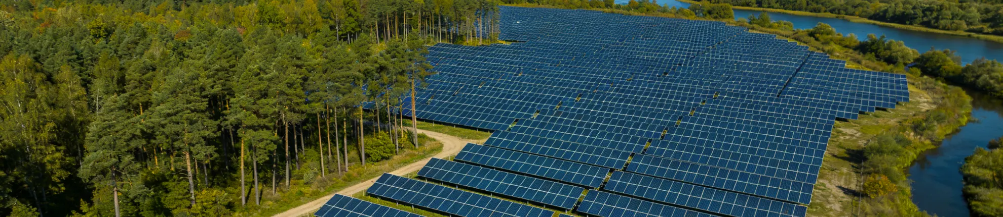
Pros and Cons of Ground-Mount Solar Racking Systems
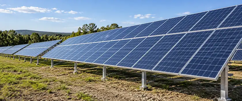
A ground-mount solar project avoids many limits set by an existing roof, but the engineering work shifts to the site itself. Usable land, terrain, soil, foundations, drainage, and environmental loads all start to shape the racking design. A site that looks spacious on a plan can still call for more structural or civil work once the survey and soil data come back. This article covers conventional fixed-tilt ground-mount solar racking. Trackers and specialized pole-mounted systems carry different design and cost considerations.
Ground-mount solar racking gives engineers more control over array orientation, tilt, row spacing, access, and system size. The main trade-offs are land use, foundation work, site preparation, and a closer dependence on terrain and soil conditions. It fits projects with enough usable land and with soil and terrain that allow a practical foundation and civil scope.
Table of Contents
- Advantages of Ground-Mount Solar Racking Systems
- Disadvantages of Ground-Mount Solar Racking Systems
- Ground-Mount vs. Roof-Mount Solar Racking
- How Site Conditions Change the Ground-Mount Trade-Offs
- When Is Ground-Mount Solar Racking the Better Choice?
- Ground-Mount Solar Racking Engineering and Supply
- Frequently Asked Questions
Advantages of Ground-Mount Solar Racking Systems
Most ground-mount advantages come from the freedom to place and shape the array. Roof geometry no longer fixes the available area, slope, or orientation, though the site brings its own limits.
More Freedom in Array Layout and Orientation
A fixed-tilt ground mount gives engineers more control over module orientation, tilt angle, row spacing, ground clearance, and PV table geometry. A PV table is the group of modules supported by one set of posts and beams.
Orientation and tilt follow the site's solar resource, seasonal production targets, shading conditions, and available land.
Row spacing is part of the same layout trade-off. Wider spacing reduces inter-row shading and leaves more working space, but it uses more land. A steeper tilt increases row height and lengthens the shadow each row casts, so the row pitch has to increase to keep inter-row shading at the same level. Engineers express that relationship as the ground coverage ratio (GCR), the module area divided by the ground area it occupies, or in row terms the collector width of one row divided by the row pitch. Tilt, row pitch, and land use are linked, so a layout cannot be optimized for energy yield and land efficiency independently.
Ground clearance affects both layout and structure. More clearance gives the array room for vegetation, uneven ground, snow accumulation, and maintenance work. Raising the array also lengthens the exposed section of each post, so the same wind pressure acts through a longer lever arm and produces a larger bending moment at the foundation. The structure has to resist that additional moment, typically through a larger post section, added bracing, closer post spacing, or deeper embedment.
Easier Access for Inspection and Maintenance
Ground-level arrays are easier to reach for visual inspection, module replacement, cleaning, wiring checks, and other routine work. Large projects also lay out access lanes for personnel and equipment from the start.
Maintenance needs do not disappear. They move to ground level, where vegetation, erosion, drainage, access routes, and the surface beneath the modules become part of normal site management. Runoff behaves differently under rows of modules than on open ground, which is why the DOE-funded PV-SMaRT project published runoff estimation tools and stormwater guidance written for ground-mounted PV sites.
Ground-level work removes the roof access requirements that rooftop maintenance involves. It also avoids the need to coordinate PV service with the building's roof warranty. Ground sites still require vegetation management, erosion monitoring, and access-road upkeep.
Array Size and Future Expansion on Ground-Mounted Sites
Available land can carry an array well beyond the capacity of a single building roof. Developers have room to set table count, row count, service access, and equipment locations around the target project capacity, while rooftop capacity stops at the usable roof area.
Future expansion is easier when suitable land remains beside the original array. Planning the first phase for additional conduit routes, transformer space, and interconnection capacity also reduces how much of that expansion becomes rework. The module footprint is only part of the total land requirement.
Disadvantages of Ground-Mount Solar Racking Systems
Foundations carry dead load, wind, and snow into the ground. Cable routes extend across the site, and terrain affects how closely the installed PV tables can follow the planned layout. Foundation, civil, and electrical work often account for more of the installed cost than the racking itself.
Ground-Mount Arrays Require Usable Land
A ground-mounted array needs space for the modules, and it needs room for everything else on the site. Before you can estimate the required parcel area, allow space for:
- Inter-row spacing
- Inspection and maintenance access
- Inverter and transformer locations
- Cable routes
- Drainage provisions
- Internal roads and equipment access
- Required site or regulatory setbacks
Acres-per-megawatt figures, or their metric equivalent in hectares per megawatt, work for early screening. They do not substitute for a project-specific layout, because land use shifts with module size, orientation, tilt, row spacing, electrical layout, site geometry, and mounting type.
The value of the land also matters. Industrial property, agricultural land, constrained commercial sites, and parcels held for future development all put a real cost on the area an array occupies.
Foundations Add Geotechnical and Civil Work
A ground mount needs a foundation that transfers dead load, wind, and snow into the soil, including the uplift and overturning forces wind produces on a tilted array.
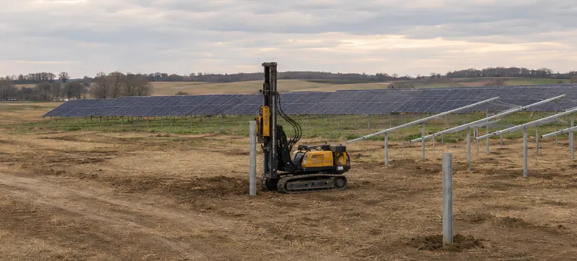
Common foundation types include driven steel piles, ground screws, helical piles, and concrete foundations. Ballasted foundations serve sites that restrict ground penetration, such as capped landfills. Shallow bedrock may require predrilling, rock anchors, or a drilled foundation, depending on rock depth and strength.
Foundation selection brings together soil conditions, structural loads, racking geometry, installation access, and local project constraints. Project teams normally review these inputs together and revisit the choice as site data arrives, since a change in soil data, loads, or installation access can change the preferred foundation type.
Changing the foundation can also change the installation equipment, the excavation or concrete work, the material quantities, the racking-to-foundation interface detail, the construction sequence, and the installation time.
The foundation and the soil therefore belong in the cost discussion from the start. Until you know how the structure will be supported at the site, a racking quotation covers only part of the cost.
Site Preparation and Electrical Routing Expand the Project Scope
Some ground-mounted projects need grading, vegetation work, trenching, access routes, or drainage improvements before the first PV table goes up.
The amount varies by site. Relatively even ground needs little earthwork. Irregular terrain may call for table-height adjustments, foundation changes, localized grading, or a different construction approach. Grading quantities affect both construction cost and schedule.
Electrical work also extends across the site. DC cabling connects the array to the inverter equipment, and AC collection carries power from the inverters toward the transformers and the point of interconnection. The project design sets the routing method, whether direct burial, conduit, or above-grade cable management. Trenching, conduit, backfill, and equipment pads add to the site construction scope alongside the racking installation.
Permitting adds its own lead time. In the U.S., ground-mount projects commonly require engineer-sealed structural drawings and a building permit, with zoning review required in some jurisdictions. Approval processes differ in other markets. Permit timelines affect when construction can start, so early site planning helps the project team account for that lead time before construction quantities are fixed.
Ground-Mount vs. Roof-Mount Solar Racking
Ground mounting and roof mounting support the same PV modules. Ground arrays rely on foundations and soil conditions. Rooftop arrays rely on the existing building and roof assembly.
Most of the differences below come from the structural interface and the area available for the array.
| Decision Factor | Ground-Mount Racking | Roof-Mount Racking |
|---|---|---|
| Available area | Usable land minus setbacks, access, and drainage | Usable roof minus obstructions, walkways, and code clearances |
| Orientation and tilt | Set by design within site limits | Influenced by roof slope, orientation, and geometry |
| Expansion | Possible where suitable land remains | Limited by remaining roof area |
| Structural interface | Foundations bearing into soil | Existing roof assembly and building structure |
| Design load path | Modules to beams, posts, foundations, and soil | Modules to rails, attachments, and roof structure |
| Maintenance access | Available from ground level | Requires roof access |
| Site preparation | May include grading, vegetation, drainage, and access work | Limited ground-related civil work |
| Main cost drivers | Racking, foundations, soil, civil work, and electrical routing | Racking, roof condition, interfaces, access, and structural capacity |
Ground mounting shifts the structural interface from the roof to the foundation and soil. Columns, beams, connections, and foundations form a continuous load path. Depending on the load case, the governing structural check may occur in the framing, a connection, or the foundation.
Difficult soil or terrain adds work to a ground-mounted project. A roof with structural, waterproofing, access, or attachment constraints adds work on the rooftop side. Project scope gives a more useful comparison than mounting location alone.
How Site Conditions Change the Ground-Mount Trade-Offs
Site conditions affect both the layout and the structural design. Terrain influences PV table elevations and installation access, soil conditions determine foundation selection, and wind and snow account for most of the structural load. These inputs are connected, so a tilt angle chosen for energy production or snow shedding also changes the wind load on the racking.
Terrain and Drainage Affect Layout and Site Work
Slope and surface variation affect PV table elevations, exposed post height, construction access, and earthwork quantities across the array.
No single maximum slope applies to every ground mount. The workable range depends on table geometry, foundation type, and the post-height adjustment built into the racking. On steep or irregular terrain, the safe working slope of the installation equipment can become the practical limit as well.
Drainage comes into the layout at the same stage. Rainwater runs off the modules and concentrates near the low edge of each row, along the dripline. Ground slope, surface cover, and drainage provisions then determine how that runoff moves across the site. On erodible soil or steeper slopes, concentrated runoff can cut channels between rows.
Erosion can also affect foundations and equipment pads. DOE flood-resilience guidance for PV systems notes that downhill flow can remove soil around piles and pads, particularly near the base of a slope.
The same guidance, written for federal on-site PV systems, also addresses prolonged soil saturation. Saturated conditions can reduce foundation support and increase corrosion risk. If prolonged saturation is expected at a site, foundation capacity and corrosion protection should be evaluated for those conditions during design.
How Soil Data Affects Foundation Design
Soil properties affect foundation size, embedment depth, installation method, and sometimes the foundation type. The same foundation geometry can therefore develop different capacities from one site to another.
Field load testing is commonly used to confirm pile or screw performance, and preliminary results are normally needed before the foundation design is finalized. Soil resistivity and other corrosivity data may also be required to select suitable below-grade corrosion protection.
At this stage a racking manufacturer will typically need the geotechnical report and any available foundation test data, along with corrosivity data where it applies. Until the foundation assumptions are confirmed, the interface details and material quantities remain preliminary.
Wind, Snow, and Exposure Define Structural Demand
Wind and snow loads transfer from the modules through the racking and into the foundations.
A steeper array sheds snow more readily, but changing the tilt also changes the projected area and the pressure distribution used in wind design. Tilt therefore affects energy production, snow behavior, structural loads, and material demand.
Snow sliding off a tilted array collects near the lower edge of each row. Once it reaches the module frame, it adds load unevenly and shades the bottom of the panel. Expected snow depth is one of the inputs behind ground clearance, alongside vegetation, terrain, flood level, and maintenance access.
For U.S. projects, Section 29.4.5 of ASCE/SEI 7-22 covers wind loads on ground-mounted fixed-tilt PV systems, which earlier editions did not cover. The tabulated method applies inside a defined set of geometric limits covering panel and row dimensions, tilt, height, row spacing, module gaps, and row count.
If the planned geometry falls outside those limits, Section 29.4.5 cannot be applied as written, and the project engineer needs a method the governing code permits. That can mean wind-tunnel data under ASCE/SEI 49-21, which adds engineering time and cost.
The governing structural code should be confirmed early. U.S. projects work to ASCE 7, while European projects apply EN 1991-1-4 together with the relevant National Annex. The engineer also needs to confirm that the planned array geometry falls within the applicability limits of the selected method, since additional analysis or testing may be required if it does not.
When Is Ground-Mount Solar Racking the Better Choice?
Ground mounting becomes the stronger option when your target capacity cannot fit the usable roof and the site has enough suitable land for the foundations, access roads, drainage, and electrical equipment.
Commercial, industrial, and larger PV projects meet those conditions regularly. The available roof may be too small for the target capacity, may have an unusable orientation or slope, may already carry other equipment, or may be off limits for PV entirely. Projects built around a specific fixed tilt, or holding land for a later phase, fall into the same group.
Difficult ground can reduce that advantage. Uncertain soil conditions, steep or irregular terrain, and high-value land all add engineering work, site preparation, and construction cost. Ground mounting makes the most sense where the available land can accommodate the required rows, foundations, drainage, and installation access without excessive civil work.
Procurement teams can obtain a more reliable racking quotation once the main site assumptions are defined. Project capacity alone does not establish post spacing, member sizes, or the foundation interface.
Ground-Mount Solar Racking Engineering and Supply
The starting point for a ground-mount solar racking system depends on how far your project design has progressed.
When racking engineering is still required, the Mibet team works from the module data, site plan, structural load criteria, and available foundation and installation information to develop the array layout and racking configuration. When the design is already complete, Mibet manufactures and supplies the racking to the approved drawings and specifications.
Depending on the agreed scope, the project package may include array layouts, structural or assembly drawings, foundation-interface details, a bill of materials, and installation documentation.
Frequently Asked Questions
1. Is ground-mount solar more expensive than roof-mount solar?
It depends more on scale and site conditions than on mounting type. Ground mounting adds foundations, grading, trenching, and access work that a rooftop array does not need, while rooftop projects add structural verification, waterproofing, attachment interfaces, and roof access requirements. Construction efficiency at larger ground-mount sites can offset a good deal of the civil scope.
A useful comparison looks at total installed scope for the same project capacity and site conditions. Racking price alone does not show the full cost difference.
2. Do ground-mounted solar panels produce more energy than rooftop panels?
Not inherently. Ground mounting does not change the conversion efficiency of the module itself.
It does give the designer more control over orientation, tilt, row spacing, and array geometry, and an open rack runs cooler than a module mounted close to a roof surface. Those differences can increase annual energy yield on some sites. Annual yield still depends on solar resource, shading, module performance, operating temperature, electrical losses, and layout.
3. Can ground-mount solar racking be installed on sloped terrain?
Yes, within limits set by the racking system and the site. Slope direction matters as much as slope angle.
Variation along a row can often be accommodated through the post-height and connection adjustment available in the racking system. Cross-row slope is harder to accommodate, because it changes the effective tilt and the row-to-row shading geometry, and it may require grading or table-height changes. A slope falling toward the equator can reduce inter-row shading, while a slope falling away from it may require greater row spacing to maintain the same shading target.
The practical slope limit depends on the post adjustment range, the foundation type, the working slope of the installation equipment, and the manufacturer's design limits.
4. What foundations are used for ground-mount solar racking?
Common options include driven steel piles, ground screws, helical piles, and concrete foundations. Sites that restrict ground penetration, such as capped landfills, may require ballast, while shallow bedrock and other difficult ground can call for drilled or anchored foundations.
The final choice depends on geotechnical conditions, structural loads, terrain, and installation access.
5. What information is needed to design a ground-mount solar racking system?
The starting inputs for your project are usually the module data sheet and quantity, module orientation, project location and site plan, target tilt, required ground clearance, structural load criteria, terrain information, site exposure conditions, and any available soil or foundation data.
Those inputs establish the geometry and the loads the structure carries. Detailed geotechnical, civil, and structural information follows as the project moves toward final design. Projects that require a test-pile program normally need those preliminary results before the foundation assumptions are finalized.
Here is a list of the sources used to create this article.
- Improving Solar Permitting by Addressing Questions about Stormwater Runoff (PV-SMaRT). U.S. Department of Energy, 2023.
- Best Practices: Photovoltaic Stormwater Management Research and Testing (PV-SMaRT). Great Plains Institute, 2023.
- Land Requirements for Utility-Scale PV: An Empirical Update. Lawrence Berkeley National Laboratory, 2022.
- Preventing and Mitigating Flood Damage to Solar Photovoltaic Systems. U.S. Department of Energy, FEMP.
- ASCE/SEI 7-22, Minimum Design Loads and Associated Criteria for Buildings and Other Structures. ASCE, 2022.
- ASCE/SEI 49-21, Wind Tunnel Testing for Buildings and Other Structures. ASCE, 2021.
- EN 1991-1-4, Eurocode 1 – Actions on Structures: Wind Actions. CEN.

Tao Chen
Marketing Director & IT Director · MIBET ENERGY
MIBET is a global designer and manufacturer of solar mounting systems. With over 10 years of professional experience, Tao Chen regularly contributes articles to our blog on structural design, installation, and maintenance, offering valuable guidance for navigating the complexities of solar projects.