How to Choose the Right Solar Pole Mounting System
Two arrays with the same number of modules can require different poles, different foundations, and different installation methods. Module dimensions, tilt, ground clearance, wind exposure, and soil conditions all change the structural demand. Foundation work, lifting requirements, and maintenance access follow from it.
This guide covers top-of-pole systems used as single-post ground mounts. Side-of-pole brackets and multi-post ground mounts follow different structural rules and are outside its scope.
Select a solar pole mounting system by matching the exact PV module and array geometry to the site loads, pole height, tilt range, soil conditions, corrosion environment, and installation plan. Panel count and rated system power do not define structural capacity. The pole, beams, rails, clamps, fasteners, and foundation all have to be checked against the same design basis and the code edition your jurisdiction has adopted.
Table of Contents
When Is a Solar Pole Mount the Right Choice?
A pole mount fits best where arrays are small, distributed, or need to stand clear of the ground. Remote power systems, agricultural sites, water-pumping installations, communications facilities, and small commercial arrays are the usual applications. It also works on sites with obstacles or irregular boundaries, because each array can be positioned independently of the others.
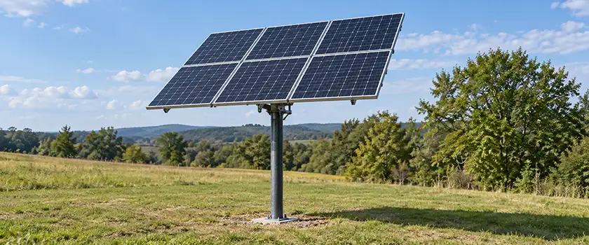
One main column carries a single PV module or a multi-module array. The space below the modules can stay usable for vegetation control, livestock movement, equipment access, drainage, snow clearance, or inspection. How much of that space you get depends on the mounting height and layout you select.
Compared with a multi-post ground mount covering the same array area, a pole mount concentrates the load into fewer support points. The number of foundation locations drops and the demand at each one rises. The result is a larger pole section, a larger foundation, and lifting equipment sized for a heavier assembly at height.
Site conditions usually determine whether a pole mount is the right form for a project.
| Project Condition | Pole-Mount Suitability | Project Implication |
|---|---|---|
| Small or distributed PV arrays | Often suitable | Each array can be positioned independently around the site |
| High ground-clearance requirement | Often suitable | The lower module edge stays above vegetation, snow, livestock, or equipment |
| Uneven or obstructed site | Case by case | Separate foundations remove the need for continuous row alignment. Slope and access still govern |
| Remote power application | Often suitable | A compact array can sit close to the electrical load |
| Large continuous utility-scale array | Compare alternatives | A multi-post ground mount usually gives a more repeatable construction sequence |
| Restricted excavation or concrete access | Case by case | Access for drilling or driving equipment at each location, plus concrete delivery where foundations are cast in place |
Installation access, available lifting equipment, and the selected foundation method also limit the practical size of a pole-mounted assembly.
Once a pole mount suits the site, the exact module becomes the next structural input. Array width, height, weight, and total surface area all come from the module datasheet, and two six-module arrays built from different modules produce different rail spans, different wind-exposed areas, and different forces at the pole base. Confirm the module model, its dimensions and weight, the permitted clamp zones, and portrait or landscape orientation before any structural configuration is fixed.
A module change late in the project can lengthen the rails, increase the wind area, shift the center of gravity, and raise the loads arriving at the pole and foundation.
How Site Loads Reach the Pole and Foundation
Wind often governs how large the pole and foundation need to be. Because the array is elevated on a single column, wind load on the module surface reaches one foundation through one member. A multi-post ground mount spreads the same load across several supports.
The design figures behind that sizing depend on the code edition your jurisdiction has adopted. In the United States, the governing standard is the edition of ASCE/SEI 7 that the local building code references. The 2021 International Building Code references ASCE 7-16, and the 2024 International Building Code references ASCE 7-22. Confirm the adopted edition with the authority having jurisdiction before any load calculation starts, because wind speed maps and pressure coefficients from different editions cannot be mixed. Projects in other markets follow the structural standard adopted by their own jurisdiction.
ASCE 7-22 also added Section 29.4.5, the first dedicated wind provisions for fixed-tilt ground-mounted solar arrays. Earlier editions covered ground mounts under general provisions for open structures, with the applicable coefficients left to project-specific engineering judgment. The new provisions were developed around arrays arranged in rows, so a single isolated pole-mounted array presents a different geometry. The structural engineer confirms whether the actual configuration falls within the applicability limits of Section 29.4.5 or requires another procedure.
Wind Design Requires More Than Wind Speed
Mapped wind speed is one input. Design wind pressure on a pole-mounted array depends on three further groups of variables.
Site and terrain. Exposure category, ridges and escarpments, and mounting height above grade. Open rural terrain and a hilltop position both raise the design pressure.
Array geometry. Array width and depth, tilt angle, and orientation relative to the design wind directions.
Code method. The pressure coefficients, gust effect, and load combinations that apply under the adopted edition.
Wind pressure and suction act across the module face, bending the pole and creating overturning demand at the foundation. Increasing the mounting height lengthens the lever arm between that force and the foundation, so the base moment rises for the same wind pressure and the same module count.
Snow Loads May Govern the Design
Snow design starts from the site snow criteria in the applicable code. The load on a tilted array then varies with slope, geometry, exposure, thermal conditions, and the provisions for balanced, unbalanced, sliding, and drifting snow.
A steeply tilted array sheds snow more readily, and ground clearance determines where that snow accumulates. With the frame close to grade, snow shed from the lower module edge can pile against it and remain as an added load. Greater clearance reduces that interaction, though it also increases the exposed pole height and the resulting wind moment.
Snow does not always slide. It can remain on the glass, refreeze, or form an uneven pattern across the array, and the calculation has to use the code provisions that apply to the site and the array geometry.
Check the Basis of a Quoted Wind or Snow Rating
A quoted wind or snow rating is tied to one array configuration and one set of design assumptions. Confirm those assumptions before applying the rating to a different project.
Ask which conditions the quoted rating was established under:
- The array configuration
- The module dimensions and total array area
- The tilt angle
- The mounting height
- The exposure category
- The code edition
Ratings are comparable between projects only when these conditions are stated alongside them.
Foundations Transfer the Load into the Soil
Loads travel from the modules through the clamps, rails, beams, the adjustment assembly on an adjustable-tilt array, and the pole. Engineers call that sequence the load path. The foundation transfers the load into the supporting soil or rock, so its design has to match the pole connection above it and the ground conditions below.
Match the Foundation to Soil and Site Access
The pole interface is the connection detail at the base of the column: a baseplate on anchor bolts cast into a pier, a socket or sleeve that the pole drops into, or a directly embedded pole section. That interface limits which foundation types can be used.
Concrete piers are common. Several other types work on pole-mounted structures when the interface and site conditions allow.
The pole section is set directly in compacted backfill or encased in concrete.
A baseplate bolts to anchor bolts cast into a cast-in-place concrete foundation.
Driven piles, helical piles, and ground screws, installed with dedicated equipment and no concrete cure time in the schedule.
Used where competent rock is accessible to the drilling equipment.
Soil profile, groundwater, frost depth, slope, drainage, subsurface rock, equipment access, installation tolerances, environmental restrictions, and local permitting all narrow that list.
Native soil and uncontrolled fill behave differently under lateral load. Loose or previously disturbed fill can provide less lateral resistance at the same depth than competent undisturbed soil. Geotechnical data let the designer characterize the material and set the design assumptions accordingly. Groundwater and poor drainage affect excavation stability, concrete placement, corrosion exposure, and long-term soil behavior.
Pole and Foundation Work as One Assembly
Pole section size and wall thickness, steel grade, unsupported height, and embedment govern the response above and below grade. Foundation dimensions, depth, reinforcement, and the surrounding soil determine how the ground restrains the pole.
Foundation demand changes if the array grows larger, the clearance increases, the tilt changes, the soil assumptions change, or an adjustable-tilt structure adds operating positions to check. If any of those change after the structural design is fixed, the pole and foundation need checking again against the revised geometry.
In frost-susceptible soils, soil bonded to the pier shaft can transfer frost-heave uplift into the foundation, lifting it as the ground heaves and leaving it slightly higher after the thaw. Repeated over several winters, that movement takes the pole out of plumb and moves the array off its design azimuth.
Local frost depth, soil moisture, and the shaft detail all bear on adfreeze uplift, which places embedment depth in the geotechnical scope.
No universal embedment depth or foundation size applies across projects. Those dimensions are determined from the site loads, the array geometry, the soil assumptions or geotechnical data, the material properties, and the design method the local code requires.
Coordinate Tilt, Ground Clearance, and Layout
Tilt affects energy production. It also changes the height and the loading of the array, so tilt, lower-edge clearance, and site layout need to be coordinated as one set of decisions.
Tilt angle. The selected angle changes solar exposure, projected wind area, overall height, and the position of the lower module edge. A fixed-tilt project balances the energy target against structural and site constraints. On an adjustable-tilt system, the pivot and locking positions define the available angles. Structural checks then cover every planned operating angle, and crews need clear access to the mechanism.
Ground clearance. Here, ground clearance means the vertical distance from finished grade to the lowest point of the module frame. On an adjustable-tilt array that distance changes with the angle, so the design uses the position producing the smallest clearance. The lower edge may need to stay above seasonal snow, vegetation, livestock, equipment, standing water, soil splash, or a maintenance route. More clearance preserves usable space under the modules. It also exposes more pole above grade and raises structural demand.
Layout. Array azimuth, spacing, slope, nearby obstructions, maintenance routes, cable paths, and electrical-equipment positions shape the final placement. Azimuth is the horizontal compass direction the modules face. Adjustable-tilt arrays also need space for the full range of motion and for worker access during adjustment.
A typical design sequence is:
- Collect the site load criteria and soil information for the location.
- Confirm the module model, its dimensions, and the array layout.
- Establish the energy target and preferred array azimuth.
- Confirm the fixed angle or the adjustment range.
- Set the required lower-edge clearance and check the resulting array height and movement range.
- Review shading, maintenance access, and cable routes.
- Verify the final geometry under the site loads.
In practice these inputs are refined together, and the geometry should be rechecked whenever the module, tilt, clearance, or foundation type changes.
Materials and Corrosion Protection
Pole mounting systems usually combine carbon steel, aluminum, and stainless steel in one structure, and service life depends on more than the base material. Alloy grade, the protective coating, the detailing at dissimilar-metal interfaces, and drainage all bear on corrosion performance, as does the site exposure itself.
Structural Materials Serve Different Functions
Each material serves a different function in the assembly and is specified for a different property.
| Material | Typical Members | Key Property | Specification Driver |
|---|---|---|---|
| Carbon steel | Poles, main beams, brackets | High stiffness at low material cost. Welds readily and comes in large structural sections | The protective coating system, selected for the exposure environment |
| Aluminum alloy | Module rails, clamps, secondary members | Oxide layer that reforms when scratched. Lower weight during installation | Alloy grade and anodizing class, matched to the exposure environment |
| Stainless steel | Fasteners and specific connection details | Corrosion resistance without a separate coating | Chloride exposure at the joint. A2 and A4 are the ISO 3506 grades in common use, with A4 often selected where chloride resistance matters |
These three materials are commonly combined, and the interfaces are where the detailing matters.
- Alloy grade and coating class should match the site exposure.
- Where aluminum, carbon steel, and stainless steel meet, isolate the surfaces or select fasteners compatible with both.
- Connection details should allow water to drain off the joint.
- Anodized surfaces resist current flow at the joint, so bonding and grounding connections need the specified bonding hardware and have to follow the applicable electrical requirements.
Coating Details at Cuts, Fasteners, and Interfaces
Corrosion performance depends on coating continuity at cuts, fasteners, and joints.
Hot-dip galvanizing immerses a fabricated steel article in molten zinc. The reaction forms metallurgically bonded zinc-iron alloy layers on the steel surface. Zinc is also anodic to steel, which means it protects small exposed areas such as scratches, cut edges, and drilled holes by corroding preferentially. How far that protection extends depends on the size of the exposed area and the environment.
Larger bare areas created by field cutting, drilling, or welding fall outside that range and may require repair under the applicable specification, where a brush-applied or sprayed coating will not match the thickness of the original bath-applied layer.
ISO 1461:2022 covers hot dip galvanized coatings on fabricated iron and steel articles, and its scope excludes galvanized products that already have their own standards. Threaded fasteners are the main exclusion, and ISO 10684 covers them from M8 to M64 while advising against hot dip galvanizing threaded fasteners below M8. Where both apply, the purchase documents should name the applicable standard for each component.
Solar Pole Mounting System Design for Your Project
The Mibet engineering team designs solar pole mounting systems based on confirmed module, site, structural load, foundation, and installation requirements.
To start, send the project location and adopted code edition, the module datasheet, the planned tilt and required ground clearance, the design wind and snow criteria, and the environmental exposure. A preliminary structural configuration can be prepared before geotechnical data are available, though foundation dimensions remain provisional until the soil design basis is confirmed.
Frequently Asked Questions
1. How many solar panels can one pole mount support?
There is no universal panel count. A rated module count states how many panels a configuration accepts. Structural capacity determines whether that configuration is suitable for the module geometry and the site loads, and it depends on module dimensions and weight, total array area, orientation, tilt, ground clearance, wind and snow conditions, pole design, and foundation.
A four-module or six-module configuration still has limits on module dimensions, frame geometry, array area, and site loads.
2. Can a solar pole mount support large-format PV modules?
Often, provided the module dimensions, clamp zones, weight, and wind area all stay within the limits of the mounting configuration.
A longer, heavier module stretches the rail span, may change where the permitted clamp zones fall on the frame, and raises both the weight and the wind area each module contributes. Check all of it against the module installation instructions before substituting one module for another.
3. Does a solar pole mounting system always need a concrete foundation?
No. Concrete piers are common, and other options include directly embedded poles, driven or helical piles, ground screws, and rock-anchored foundations.
The available options depend on the pole interface, the structural loads, soil and groundwater conditions, installation equipment, and local requirements.
4. Can a pole-mounted solar array be installed on sloped or rocky ground?
Yes, in many cases. The design has to account for equipment access, drainage, pole alignment, foundation installation, array orientation, ground clearance, and the depth at which competent rock begins.
On some sites the foundation method is the main change, though the revised ground profile can also affect pole height, clearance, alignment, and connection details.
5. Can an existing solar pole mount be reused with new PV modules?
Possibly. Compare the new module dimensions, weight, frame section, clamp zones, mounting holes, and total array area against your original design limits. The existing structure and its connections also need inspection for corrosion, damage, and any changes made since installation.
Reuse further depends on whether the pole, beams, rails, fasteners, corrosion protection, and foundation remain suitable for the revised array. The code and load criteria used for the original design may also differ from current requirements.
Here is a list of the sources used to create this article.
- 2021 International Building Code (IBC). ICC.
- 2024 International Building Code (IBC). ICC.
- ASCE/SEI 7-22, Minimum Design Loads and Associated Criteria for Buildings and Other Structures. ASCE, 2022.
- Deep Foundations Institute. Frost Heave, Section 5.22. DFI Library.
- American Galvanizers Association. Corrosion Protection for Steel.
- American Galvanizers Association. Repairing HDG Steel (ASTM A780).
- ISO 1461:2022, Hot Dip Galvanized Coatings on Fabricated Iron and Steel Articles: Specifications and Test Methods. ISO, 2022.
- ISO 10684:2004, Fasteners: Hot Dip Galvanized Coatings. ISO, 2004.
- ISO 3506-1:2020, Fasteners: Mechanical Properties of Corrosion-Resistant Stainless Steel Fasteners, Part 1. ISO, 2020.

Tao Chen
Marketing Director & IT Director · MIBET ENERGY
MIBET is a global designer and manufacturer of solar mounting systems. With over 10 years of professional experience, Tao Chen regularly contributes articles to our blog on structural design, installation, and maintenance, offering valuable guidance for navigating the complexities of solar projects.