How Top-of-Pole Solar Mounts Work as a Structural System
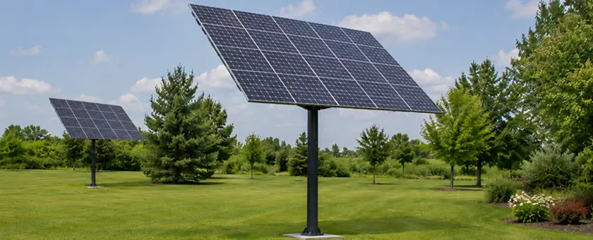
A top-of-pole solar mount looks simple on a layout drawing: a PV array, a support frame, and one pole underneath. Module size, tilt angle, and ground clearance decide what that pole has to carry. Panel count describes none of them.
A top-of-pole solar mount carries load from the PV modules through the clamps, rails, main beam, pole-head connection, pole, and foundation into the ground. Every one of those loads reaches a single vertical support, so what the mount can carry depends on array geometry, wind and snow criteria, pole section and height, connection design, and foundation conditions working together. Panel count does not define structural capacity.
Table of Contents
- What Makes a Top-of-Pole Solar Mount a Structural System?
- Top-of-Pole vs Side-of-Pole Mounting
- Main Structural Components of a Top-of-Pole Solar Mount
- How Loads Travel from the PV Modules to the Foundation
- What Determines the Structural Capacity of a Top-of-Pole Mount?
- Top-of-Pole Mounting Design and Supply
- Frequently Asked Questions
What Makes a Top-of-Pole Solar Mount a Structural System?
Every load acting on the array reaches the ground through one continuous path, collected at a single vertical support. Whichever part of that path reaches its design limit first sets the capacity of the whole mount.
The arrangement itself is simple. A top-of-pole mount holds a PV array above one vertical pole. The support frame beneath the modules forms the upper part of the structure, and wind, snow, and dead load pass through it into the pole, then through the foundation into the supporting ground.
If you are preparing a mounting layout or a request for quotation, the module arrangement is only part of the input. Pole height, the pole-head connection, site loads, and foundation conditions all affect the final structure.
Top-of-Pole vs Side-of-Pole Mounting
Top-of-pole and side-of-pole mounts differ in where the array sits relative to the pole, and that position changes the load path.
The support frame carries the array above the pole. The resultant load arrives close to the pole centerline.
A smaller bracket assembly fixes to the side of the pole, holding the array off that centerline. Wind pushing on an offset array twists the pole about its own length, and the array's weight adds bending a centered array does not produce.
A multi-pole ground mount spreads a larger continuous array across several posts, so no single column collects the whole load. Array size, site conditions, installation requirements, and maintenance access decide which arrangement suits a given project.
Main Structural Components of a Top-of-Pole Solar Mount
Component names vary between designs. One product may combine several functions into a compact welded frame. Another may use separate rails, cross members, bracing, and a main beam. The load-transfer functions stay the same either way. The table below follows the structure from the modules down to the foundation.
| Structural Element | Primary Role | Transfers Loads To |
|---|---|---|
| Module clamps | Hold the modules within the clamping zones approved by the module manufacturer | Rails |
| Rails (called purlins in some product lines) | Support the modules and spread local loads | Cross members and main beam |
| Main beam and cross members | Carry the assembled PV array | Pole-head connection |
| Bracing and tilt members | Hold the frame geometry and set the tilt angle | Main beam and pole-head connection |
| Pole-head connection | Join the support frame to the pole | Pole |
| Pole | Carry vertical and lateral loads, resist bending moments | Base plate or embedded section |
| Base plate and anchor bolts, or the embedded pole section | Transfer pole reactions into the ground | Foundation and supporting soil |
The support frame spreads load across the whole array, and the pole-head connection passes the combined reactions into a single pole. Vertical force, lateral force, and bending all move through that one connection. A change in array geometry changes what that connection carries.
How Loads Travel from the PV Modules to the Foundation
Load accumulates as it moves down a top-of-pole mount, so the load path matters more than any single component rating.
- PV modules
- Module clamps
- Rails
- Main beam
- Pole-head connection
- Pole
- Foundation
- Soil
Each member passes what it receives to the next one. A rail can meet its own load rating while the beam, the connection, the pole, or the foundation beneath it governs the design.
In the U.S., ASCE/SEI 7-22 sets the minimum design loads for that path. The applicable edition depends on the building code the jurisdiction has adopted, and the 2024 IBC references ASCE 7-22 in place of ASCE 7-16.
Dead Load and Snow Load
Dead load is the permanent weight of the installed structure: modules, rails, beams, bracing, clamps, and fasteners. It acts continuously and is the easiest load to quantify.
Snow load varies far more. The design value starts with the ground snow load mapped for the project location, then is adjusted for site exposure and array tilt. A steeper array sheds snow faster than a shallow one, so the slope factor reduces the design load as tilt increases. Two mounts with identical module layouts can carry different design snow loads in the same climate, one at a steeper tilt in open terrain and the other at a shallower tilt among sheltering trees.
Snow does not always leave a tilted array evenly. If one part unloads before another, the resultant sits off the pole centerline as an eccentric vertical load. A multi-post ground mount spreads that eccentricity across several columns; a top-of-pole mount takes it at one connection, as added bending at the pole head. The governing case, uniform or partial, follows from the structure and the applicable design provisions. Published capacities should state which load case they cover.
Wind Creates More Than a Horizontal Force
An elevated PV array behaves as an open structure in wind. Air passes above and below the tilted plane, and the net pressure across the modules acts downward or as uplift depending on wind direction and tilt. That pressure reaches the pole as lateral force and bending, and reaches the foundation as overturning.
The provisions that produce that pressure do not all apply to a single-pole array. ASCE 7-22 added Section 29.4.5 for ground-mounted fixed-tilt PV, and its scope is written around arrays installed in rows: the limits start at three rows, all with the same chord length. One array on a single pole falls outside those limits, so its wind coefficients do not come from that section, and the engineer of record selects the applicable procedure.
Ground clearance changes the geometry that pressure acts through. Raising the array moves the point where wind force acts farther from the base, which lengthens the lever arm. The design velocity pressure is a separate matter. It increases with height above grade, but the exposure coefficient comes from a table whose lowest band spans several feet, and a clearance change inside that band leaves it unchanged.
Engineers call that distance the lever arm: the perpendicular distance from a force's line of action to the point about which it rotates the structure. For a lateral force F acting at height h above the base, the overturning moment is the product of the two, M = F x h. A full wind check combines several pressures acting at different heights, and the design moment comes from the governing load combination.
For a base-plated pole, bending demand is highest near the base connection. An embedded pole is restrained by the surrounding soil below grade, and its moment distribution follows the embedment depth and the soil stiffness. Greater ground clearance raises the overturning demand at the bottom of the structure, since the wind force acts through a longer lever arm. Two mounts with the same modules and the same tilt can need different pole sections and different foundations if only their clearances differ.
Array height, tilt, and layout should be confirmed before the final structural calculations and foundation design are issued. A later dimensional change means revising both. Exposure category, design wind speed, and the required ground clearance all belong in the project inquiry.
What Determines the Structural Capacity of a Top-of-Pole Mount?
Capacity is one half of the check. The array and the site set the loads: module dimensions and mass, array geometry, tilt, ground clearance, and the local wind and snow criteria. The member sections, connections, pole, and foundation provide the resistance available to meet them. Module count sits inside the first group and describes only part of it.
Why Panel Count Alone Is Not a Structural Rating
Labels such as four-panel mount or six-panel mount describe a product configuration. The panel-count label by itself is not a structural rating.
PV modules differ in length, width, mass, and in the clamping zones their manufacturers approve. Six large-format modules produce a different array width, height, exposed area, rail span, and frame geometry from six smaller ones. The frame has to suit the modules that will be installed.
Wattage does not close that gap. Mounting design works from the physical data on the module data sheet rather than the power rating: dimensions, mass, and the clamping zones marked in the installation manual.
Confirm the module manufacturer's approved clamping zones early. Clamping outside them can void the module warranty and put bending into the laminate where it has the least support.
Array Geometry Changes Structural Demand
Sizing a specific mount means working several inputs at once, the first five from the array and the next three from the site.
| Design Input | Structural Relationship | Project Implication |
|---|---|---|
| Module dimensions | Set array dimensions and support geometry | Change rail and beam layout |
| Module quantity | Changes total array area and dead load | Influences overall frame size |
| Module orientation | Changes array proportions and member spans | Can require a different support arrangement |
| Tilt angle | Changes frame geometry and wind response | Sets bracing, connection, and member demand |
| Ground clearance | Lengthens the wind-load lever arm, and may also raise the design pressure | Raises pole base bending and foundation demand |
| Wind criteria | Set lateral, uplift, and downward wind actions | Size members, connections, pole, and foundation |
| Snow criteria | Add uniform and partial loading cases | Affect the vertical load path and member sizing |
| Foundation and soil conditions | Control how loads enter the ground | Set foundation type and dimensions |
| Pole section and height (follows from the above) | Govern support stiffness and bending capacity | Must match the reactions from the frame above |
These relationships are general, and the design values are project-specific. Two six-module arrays show the gap. If one uses large-format modules and sits higher above grade, both its exposed area and its base moment are higher — same module count, different structural problem.
Module quantity is a reasonable opening line in an RFQ. The structure comes from the rest of the set: the module data sheet, orientation, planned tilt, required ground clearance, the project location, and the applicable wind and snow criteria. Tilt and ground clearance come first among those, since both set the array geometry the calculations start from.
The Foundation Is Part of the Capacity
The foundation receives vertical force, lateral force, and overturning moment from the pole, and on a single-post structure all three arrive at the same point. For an embedded pole, soil stiffness affects the lateral restraint, the deflection, and the embedment depth required.
The mounting supplier provides the base reactions. The engineer responsible for the foundation design checks those reactions against the site geotechnical data.
Top-of-Pole Mounting Design and Supply
The Mibet engineering team designs and supplies top-of-pole solar mounting structures for specific projects. We work from the module specifications, array layout, tilt, ground clearance, project location, applicable wind and snow criteria, and any available soil or foundation information.
Those inputs define the mounting layout, member sizes, pole section and connection details, component scope, drawings, bill of materials, and the base reactions needed for the foundation design.
Frequently Asked Questions
1. Can an existing pole be reused for a top-of-pole solar mount?
Possibly. Reuse depends on the pole material, section, height, condition, connection details, existing foundation, and the loads the proposed PV array adds.
A reused pole was installed for a different load case, so both the pole and its existing foundation need checking against the added PV loads. A records-based review needs the original pole section and material, the foundation details, and the embedment depth. Without those records, your options are field investigation or treating the installation as new construction.
2. Does a top-of-pole solar mount always need a concrete foundation?
No. Several foundation types suit these structures.
Foundation selection depends on structural loads, pole arrangement, soil and site conditions, construction access, and local design requirements. The selected foundation transfers the pole reactions into the ground under the project design conditions.
3. Can top-of-pole solar mounts use adjustable tilt?
Yes, provided the supporting structure is checked for every permitted tilt position.
Tilt changes the array geometry exposed to wind, so the governing position can vary by load case. The adjustment mechanism is part of the load path, and its pins or bolts must transfer the design reactions at each permitted position. For seasonal adjustment, the product's permitted tilt range should cover every intended position.
4. Can portrait and landscape modules use the same top-of-pole structure?
Sometimes. Orientation changes array proportions, rail positions, member spans, beam lengths, and connection geometry, so a frame sized for one orientation may not suit the other.
A mounting system may accept both. The arrangement that applies must match the actual module dimensions and the clamping zones the module manufacturer approves.
5. What materials are commonly used in top-of-pole solar mounting structures?
Structural steel for poles and major load-bearing members, aluminum for some rails and mounting members, and corrosion-resistant fasteners chosen for the site.
Steel and aluminum in contact can form a galvanic couple wherever moisture connects them electrically, and the less noble metal corrodes faster at the joint. Galvanizing changes the pairing, since the zinc coating sits between the two. Severity varies with the exposure, and isolating washers or bushings are specified where the site is aggressive.
Site conditions set how much protection the steel needs. ISO 9223:2012 classifies atmospheric corrosivity from C1 through C5 plus CX, working from how long surfaces stay wet, sulfur dioxide pollution, and airborne salinity. The category comes from the actual exposure at the site. CX is the extreme end of the range, reserved for severe marine and marine-industrial conditions, and a coastal location does not necessarily fall there.
Batch hot-dip galvanizing to ISO 1461:2022 is a common protection option for steel parts within the standard's scope, with minimum coating thickness set by the thickness of the article. Corrosion conditions differ above and below grade, so the groundline and the buried section are considered separately.
Here is a list of the sources used to create this article.
- ASCE/SEI 7-22, Minimum Design Loads and Associated Criteria for Buildings and Other Structures. ASCE, 2022.
- ISO 9223:2012, Corrosion of metals and alloys — Corrosivity of atmospheres — Classification, determination and estimation.
- ISO 1461:2022, Hot dip galvanized coatings on fabricated iron and steel articles — Specifications and test methods.

Tao Chen
Marketing Director & IT Director · MIBET ENERGY
MIBET is a global designer and manufacturer of solar mounting systems. With over 10 years of professional experience, Tao Chen regularly contributes articles to our blog on structural design, installation, and maintenance, offering valuable guidance for navigating the complexities of solar projects.