Common Structural Types of Steel Solar Carports
Most of what separates one steel solar carport from another comes down to where the columns stand. Column position sets how much room vehicles have at ground level, how far the beams span or cantilever, and what the foundations carry. Frame shape has to work with it. The names are looser, and the same structure can appear on two drawings under two different labels, which is why comparing carport proposals usually starts with figuring out what each one actually describes.
Common steel solar carport structures include single-post cantilever, double-cantilever or T-frame, Y- and V-frame, dual-post, and multi-column configurations. The terms describe different aspects of a carport, including column arrangement, frame geometry, and parking coverage, so the categories overlap. The appropriate configuration depends mainly on the parking layout, available column locations, canopy span, project-specific design loads, and foundation conditions.
Table of Contents
- How Are Steel Solar Carport Structures Classified?
- Five Steel Solar Carport Configurations and Their Load Paths
- Steel Solar Carport Structural Types Compared
- Which Structural Type Fits Different Parking Layouts?
- Loads, Spans, and Foundations Follow the Configuration
- How to Choose the Right Steel Solar Carport Structure
- From Parking Layout to Solar Carport Design
- Frequently Asked Questions
How Are Steel Solar Carport Structures Classified?
Steel solar carport names usually describe three aspects of the structure.
Where the primary supports stand. A carport may have one main support line, two support lines, or several rows of columns. Terms such as single-post, dual-post, and multi-column refer to support placement.
How the columns and main beams carry the canopy. Cantilever, T-frame, Y-frame, and V-frame are common frame descriptions. Frame geometry sets the load path: the route that loads follow from the modules through the purlins, main beams, columns, and base connections into the foundations.
The parking rows beneath the canopy. A structure may cover one row, two back-to-back rows, or a larger repeating parking area. Single-row and double-row say more about the parking layout than about the structure itself.
These descriptions overlap because the vocabulary we use for carports covers several things at once. A carport with one central column line may form a T-shaped frame and extend to both sides over two parking rows. Depending on the feature being described, that same structure gets called a single-post carport, a T-frame, a double cantilever, or a double-row carport. Each label describes a valid aspect of the same layout, none covers the whole of it, and supplier terminology varies on top of that.
Five Steel Solar Carport Configurations and Their Load Paths
Single-Post Cantilever Solar Carports
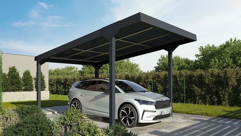
A single-post cantilever carport places its main support line along one side of the covered parking area. The main beam cantilevers out over the vehicles from that line, and the far side stays open at ground level.
Perimeter and single-row parking often leave a workable column zone near a curb or boundary. Keeping the columns off the open side leaves room for vehicles, door swing, and pedestrians.
The canopy load travels along the cantilever to the support line. For an idealized prismatic cantilever under uniform load, the support moment is wL2/2 and the tip deflection wL4/(8EI). Moment varies with the square of the projection, deflection with its fourth power. Extending the overhang by 20 percent raises the support moment by about 44 percent and roughly doubles the tip deflection. On wide canopies, deflection often reaches its limit before strength does.
That bending has to be resolved at the base. A single-post column carries the overturning moment straight down to its foundation, so the base connection has to resist moment, and the footing or pier is sized for moment as well as vertical load. With only one support line, one line of foundations takes all of it. Column position usually drives this choice.
Double-Cantilever or T-Frame Solar Carports
A T-frame rises from a central column line and carries canopy framing out to both sides. In structural terms, most T-frame carports work as double cantilevers.
The arrangement fits between two back-to-back parking rows when the center divider can take columns and foundations. One support line serves both rows, and the outer parking edges stay clear of columns.
The two sides will not always be loaded equally. Under symmetric gravity load, the moments from the two cantilevers largely cancel at the column. The column then carries mostly axial force. Unbalanced snow, one-sided wind uplift, or a module layout that stops short on one side will break that balance, and the difference between the two sides travels through the column to the foundation as a net moment. That unbalanced case often governs the column section and the foundation, even though the symmetric case carries the larger total load.
Y-Frame and V-Frame Solar Carports
Y- and V-frames both place inclined members between the column and the canopy, and the difference is in how those members are arranged. A Y-frame carries a single column up to a branch point, where two inclined arms pick up the canopy framing. The V-frame label is less consistent across suppliers. It can mean inclined members converging toward a single base point, or a canopy whose two halves tilt toward each other into a shallow V.
Moving the upper support points inboard from the beam ends shortens the effective cantilever on each side and creates an interior span between them. Where the branch points sit far enough out, that redistribution lowers the peak moment for the same overall canopy width. The inclined members also carry load mainly in axial compression or tension. Axial force uses steel more efficiently than bending does, though compression members still need buckling and connection checks.
On commercial sites where the carport is visible from the street or the building entrance, appearance becomes part of the brief. Capacity is a separate question, settled by member sections, connections, span, and design loads.
Dual-Post or Two-Column Solar Carports
Dual-post carports place two support lines beneath the canopy. The second line shortens the clear span and shares reactions across more columns.
For the same span and load, the peak moment on a cantilever is four times the mid-span moment of a simply supported beam, wL2/2 against wL2/8. For the same material and bending criterion, required section modulus scales with moment, so the idealized comparison points to a quarter of the section modulus. Actual sizing comes from the complete frame model, where deflection and stability checks also apply.
Base conditions change too. With two support lines, frame action or bracing can provide the lateral stability, so pinned column bases become an option and moment demand at each footing drops. A single-post column has no equivalent path in the cantilever direction. Its base is the only place that overturning moment can go.
Multi-Column Solar Carports
A multi-column carport divides a larger canopy into repeated structural bays on a regular column grid.
Shorter bays reduce main-beam bending demand and allow shallower beam sections. Total steel does not fall in step with that, since every added bay brings its own column, base plate, connections, and foundation.
Each support is a point where the structure meets the civil design, and every one needs a workable foundation position within a grid that aligns with the stalls, traffic circulation, drainage, and underground utilities. Bay spacing also has to be coordinated with the purlin layout and the module dimensions above. Poor coordination can leave partial-width zones at bay boundaries, or call for extra secondary framing to carry the modules across them.
Steel Solar Carport Structural Types Compared
The table sorts the configurations by number of support lines, the one axis that holds across all of them. The relationships are typical, not fixed design rules.
| Support Arrangement | Drawing Callouts | Structural Characteristic | Foundation Implication |
|---|---|---|---|
| One support line, cantilevered to one side | Single-post cantilever, single-sided carport | Full canopy moment resolved at one line of columns | Moment-resisting bases, overturning concentrated on one foundation line |
| One support line, cantilevered to both sides | T-frame, double cantilever | Opposing cantilever moments largely cancel under symmetric load | Net base moment set by the unbalanced load cases |
| One support line with inclined members | Y-frame, V-frame | Inclined members carry load axially and shorten the effective cantilever | Reactions still resolve at one column line, with moment reduced where the branch points shorten the effective cantilever |
| Two support lines | Dual-post, two-column | Clear spans shorten, and beam bending demand drops | Pinned bases possible where bracing or frame action provides stability |
| Multiple support lines | Multi-column, repeating bay grid | Repeated bays distribute load across many supports | Loads shared across more supports, with more foundation locations required |
Which Structural Type Fits Different Parking Layouts?
Perimeter and single-row parking usually points to a single-post cantilever. Back-to-back rows point to a central support line, and a large lot to a repeating column grid. All three follow from where a column and its foundation physically fit, and your site plan answers that long before any member gets sized.
During early planning it helps to work with a column zone, an area where a column and its foundation fit without conflicting with parking, traffic, underground utilities, or required clear routes.
Some of those routes carry fixed dimensions. Where a carport crosses or borders a designated fire apparatus access road, the International Fire Code sets an unobstructed width and vertical clearance over the lane. The ADA Standards separately set a clear width along an accessible route.
Minimum dimensions taken from the published code text, both fire-lane figures measured unobstructed. Which edition and which amendments apply comes from the jurisdiction, and other countries set their own equivalents.
Those two dimensions govern where columns can stand and how low the canopy can sit over a lane, so they are worth marking on the parking plan before column positions go out for pricing.
On a large lot the question changes from which frame to which grid. Column spacing gets set by the parking bays below and the module layout above, and that spacing then repeats across the whole site. Shift the grid by half a stall and every foundation in every row moves with it. Some may land in a utility easement, and excavation sequencing, drainage slopes, and installation order all have to be redrawn behind them.
The usual project sequence makes that harder. Concept parking layouts are often developed while geotechnical and utility information is still incomplete, so column positions get validated late, when changing them costs the most. Keeping your parking plan and the structural concept open through that stage leaves more room to move than committing to a frame shape early.
Loads, Spans, and Foundations Follow the Configuration
The design standards set the loads and the member rules. The parking layout and the site conditions settle where the columns can go.
For U.S. projects, ASCE/SEI 7-22 gives minimum design loads and load combinations for wind, snow, seismic, dead, live, rain, and other applicable hazards, and ANSI/AISC 360-22 covers the design of structural steel members and connections. In Europe, EN 1993 covers steel design, EN 1991 gives the actions, EN 1990 sets the combinations, and the National Annex fixes the values that apply in each country. The second-generation Eurocodes are in transition, with the first generation withdrawn by March 2028, so confirm the edition in force in the project country.
Wind, Snow, and Seismic Conditions Can Change Which Frame Fits
Two sites with the same canopy dimensions can end up with different structures because the governing loads differ. For an open canopy, wind is the usual starting point.
A carport canopy is an open structure. Wind reaches the top surface and the underside at the same time, and the design value is the net pressure across both faces. Under uplift, the load path described earlier runs backwards. Load that normally travels down from the modules into the ground reverses direction, the anchors go into tension, and the foundation holds the structure down.
Pressure also climbs faster than speed does. Velocity pressure varies with the square of the design wind speed in both ASCE 7-22 and EN 1991-1-4, so with the other wind factors held constant, a site mapped at 150 mph sees roughly 1.44 times the velocity pressure of a site at 125 mph. Exposure, height, topography, and the pressure coefficients then convert that into the design pressure on the canopy.
Snow works through several separate mechanisms, and the governing standard treats them separately. The balanced load comes from the ground snow load and the roof's exposure, thermal condition, and slope. Depending on the geometry, the code may also call for partial loading, unbalanced loading, drift, or sliding-snow cases. For a double cantilever, an asymmetric snow load across the two sides produces the net base moment described earlier, and that case can govern the column and its foundation.
Seismic forces scale with the effective seismic weight, and an open steel carport is light compared with a building of the same footprint. Modules and purlins still count toward that weight, and site hazard, structural period, and the system's response modification factor all enter the result. Wind often governs lateral design for structures this light. Both load cases still have to be run before that holds for a given site.
Foundation Demand Follows the Structural Reactions
The foundation starts with the reactions the steel frame transfers. The full chain runs:
- PV modules
- Purlins
- Main beams
- Columns
- Base connections
- Foundations
- Ground
Under uplift the same chain runs the other way, from the canopy back through the anchor bolts and out through the foundation's own mass and embedment.
That reversal matters for carport foundations. Uplift and overturning frequently size an exposed cantilever base, which puts the emphasis on foundation weight and embedment depth. Which condition governs depends on the reactions, the foundation type, and the soil, so bearing, sliding, lateral resistance, settlement, and anchor or pile capacity may all need checking.
Footing, pile, and anchor design sits past the point of selecting a structural type. A dedicated guide to solar carport foundation design covers it in full.
How to Choose the Right Steel Solar Carport Structure
The order below keeps options open. Changing canopy projection or column count late is rarely a single-line revision to the beam schedule, because connection details, base plates, anchor design, and foundation drawings all move with it.
- Map the parking layout. Establish the number and orientation of parking rows, stall dimensions, aisle widths, center dividers, pedestrian routes, and which column zones are usable.
- Fix the clearances. Confirm the canopy clear height and the vehicles the site has to serve. Measure clear height to the lowest obstruction inside the required clearance envelope. Depending on the design, that may be a beam, a purlin, a gutter, a luminaire, or a cable tray, and a deeper section for a longer cantilever reduces the available clear height further.
- Establish the structural design conditions. Define canopy dimensions, required spans, module type and arrangement, wind and snow conditions, seismic requirements, and the governing standard together with its edition.
- Test the layout against foundation and site constraints. Check geotechnical conditions, existing pavement, drainage, underground utilities, property boundaries, and permitted excavation areas against the candidate column positions from step 1.
- Coordinate the attached systems before detailing. Cable routing, drainage, lighting, signage, and EV charging equipment get resolved once the structural concept is stable and before fabrication drawings are frozen. Their loads, attachment points, and clearance requirements feed back into member positions and connection details.
The result may be a single-post cantilever, a T-frame, a Y- or V-frame, a dual-post arrangement, or a multi-column grid. The first four steps decide it.
Structural type is one part of a wider solar carport mounting system selection, which also covers module geometry, required clearances, and whether the canopy has to shed water in a controlled way.
From Parking Layout to Solar Carport Design
Standard structural types give a project team a starting point. Mibet develops the frame from the parking layout, module specifications, canopy dimensions, and design conditions. Deliverables can include structural layouts and connection design, foundation reactions, a bill of materials, and installation drawings.
Send those inputs and Mibet can prepare a technical proposal and quotation for the steel solar carport structure.
Frequently Asked Questions
1. Can a single-post solar carport cover two rows of parking?
Yes. One central support line can carry a canopy that covers two parking rows, with the framing cantilevering or branching out to both sides, as in many T-, Y-, and V-frame arrangements.
Whether it works on your site comes down to canopy width, column spacing, clearance requirements, and whether the center divider can take the foundation that the unbalanced load cases call for.
2. Does a cantilever solar carport need a larger foundation?
Per foundation, usually yes. For the same canopy area and soil conditions, a cantilever column base carries overturning moment along with vertical load, so the footing or pier is sized for both and typically ends up deeper or wider than a base carrying vertical load alone.
The project total runs the other way, since a cantilever layout has fewer support lines and therefore fewer foundations to build. Final sizes still come from the soil, the foundation type, and the complete frame design.
3. Are Y-frame solar carports stronger than T-frame solar carports?
Not inherently. Capacity comes from member sections, connections, span, design loads, and the foundation system. Both geometries can be sized for the same conditions.
There is a real geometric difference behind the question. Depending on where the branch points sit, the inclined members on a Y-frame shorten the effective cantilever and move part of the demand into axial force, so the frame can run at a lower peak moment than a plain double cantilever of the same canopy width. That geometric advantage does not by itself establish the overall structural capacity.
4. Can the same steel solar carport structure be used in high-wind or heavy-snow locations?
The same general configuration often still suits the site, but the structure has to be checked against the project's own wind and snow loads. Member sizes, connections, anchors, column spacing, and foundations may all change as a result, and extreme conditions can push the choice toward a different configuration altogether.
Holding the other wind factors constant, velocity pressure varies with the square of the design wind speed, so a modest increase in wind speed moves the pressures up much further. Snow regions can introduce load cases that do not apply in mild climates.
Here is a list of the sources used to create this article.
- International Fire Code, Section 503: Fire Apparatus Access Roads. ICC, 2024.
- 2010 ADA Standards for Accessible Design. U.S. Department of Justice.
- ASCE/SEI 7-22, Minimum Design Loads and Associated Criteria for Buildings and Other Structures. ASCE, 2022.
- ANSI/AISC 360-22, Specification for Structural Steel Buildings. AISC, 2022.
- EN 1991, Eurocode 1 – Actions on Structures. CEN.
- EN 1990, Eurocode – Basis of Structural Design. CEN, 2002.
- EN Eurocodes: National Implementation and National Annexes. European Commission JRC.
- Second Generation of the Eurocodes. European Commission JRC.

Tao Chen
Marketing Director & IT Director · MIBET ENERGY
MIBET is a global designer and manufacturer of solar mounting systems. With over 10 years of professional experience, Tao Chen regularly contributes articles to our blog on structural design, installation, and maintenance, offering valuable guidance for navigating the complexities of solar projects.