Solar Carport Mounting System Selection Guide
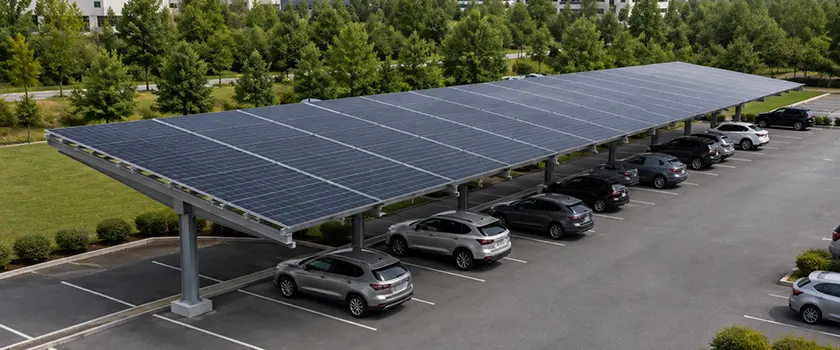
A solar carport can look straightforward on a site plan until the parking layout starts dictating where the structure can actually stand. Move a column clear of a vehicle door and the beam has a longer reach. Raising the canopy for van access changes its wind exposure, and rainwater protection adds a drainage path to the framing. These requirements interact, so system selection starts with the site, the parking use, and the design conditions, and the frame type follows from them.
The right solar carport mounting system matches the parking layout, module geometry, required clearances, design loads, ground conditions, rainwater-management needs, and installation constraints. Single-post, dual-post, and multi-column layouts place different demands on the beams, columns, connections, and foundations. Final member sizes and foundation interfaces are checked against the confirmed project inputs and the design basis adopted for the site.
Table of Contents
- What Determines the Right Solar Carport Mounting System?
- Parking Layout and Vehicle Access Constrain the Column Grid
- How Single-Post, Dual-Post, and Multi-Column Frames Differ
- Define the Module Layout, Span, Tilt, and Clearance
- Wind, Snow, and Site Exposure Change the Design Forces
- Does the Project Need a Watertight Canopy?
- What Project Information Should You Send the Manufacturer?
- Solar Carport Mounting Solutions for Your Project
- Frequently Asked Questions
What Determines the Right Solar Carport Mounting System?
System selection usually comes down to seven project inputs: the parking layout, the module geometry, the required clearances, the design loads, the ground conditions, the rainwater-management requirement, and the shipping, site access, and erection constraints.
A carport frame is assembled from columns, main beams, purlins or module-support rails, bracing, connections, and foundation interfaces, and each input shapes a different part of that assembly. The parking plan sets the column arrangement, the cantilever length, and the span. Module layout and clearance fix the canopy dimensions and the required frame height. Wind and snow criteria size the members, bracing, and connections. Ground conditions and the rainwater-management requirement shape the foundation interface and the module-joint detailing. Site access and construction phasing affect member segmentation, shipping, and the erection sequence.
Two projects can specify the same PV module and cover the same number of stalls and still need different structures, because a different constraint dominates on each site. One may have restricted column zones, another a higher snow load, and a third a requirement to collect rainwater and route it away from the parking area.
Parking Layout and Vehicle Access Constrain the Column Grid
The parking plan is usually the first drawing to limit the frame, because every column occupies usable space at ground level. Before member sizes are finalized, the project team needs to establish where supports can stand without disrupting parking, traffic flow, pedestrian movement, or required clearances.
Column Placement Must Preserve Parking Access
Useful layout information includes:
- Parking-space boundaries and drive aisles
- Curbs and pedestrian routes
- Accessible spaces and the clear widths they require
- Existing equipment
- Any zone that has to stay clear of structural supports
A column in the middle of a stall shows up immediately on the parking plan, and the smaller shifts matter as well. A support set close to a stall line can block a door from opening fully. Moving it farther from the stall line improves access at ground level and lengthens the beam reach over the parking area.
A clear span is the open distance between two supports. A cantilever extends past its support and covers ground with no column at the outer edge. As either distance grows, bending moment, deflection, connection forces, and column-base reactions all increase, and they do not increase at the same rate.
For a uniformly loaded cantilever of a given section, extending the overhang by 20% raises the bending moment at the support by roughly 44% and about doubles the tip deflection, because moment scales with the square of the overhang and deflection with the fourth power. Both figures are illustrative. Real sections, load combinations, and support stiffness change the result. In this idealized case deflection grows faster than bending moment, so even a modest change on a parking drawing can push a beam up a section size.
Vehicle Type Sets the Required Clear Height
Passenger cars, delivery vans, fleet vehicles, and service vehicles call for different clear heights and different room to maneuver. Raising the clearance raises the beam elevation, and the canopy above that line still needs depth for the framing, the module tilt, drainage components, and cable routing.
If your parking plan mixes passenger stalls with van bays, fleet parking, or a service lane, mark those zones on the drawing before column positions go out for pricing. Changes made after the column and foundation positions are fixed may require foundations to be repositioned or redesigned.
How Single-Post, Dual-Post, and Multi-Column Frames Differ
Once the usable column zones are established, the frame can be arranged around them.
Terms such as single-post, dual-post, T-shaped, Y-shaped, and V-shaped work as shorthand, and manufacturers do not always apply them the same way. The more useful comparison is the actual column arrangement and the load path, meaning how loads pass from the modules through the framing and columns into the foundations.
Single-Post Cantilever Structures
A single-post carport places one main column line along a parking divider, a median, or another available support zone, and the beams cantilever outward over the parking area.
The open side leaves more ground-level room around parked vehicles, and the same geometry concentrates demand at the cantilever support as covered width and design loads grow. Main beam, column, connection, base plate, anchors, and foundation work as one load path. A longer cantilever raises the bending demand at the support and the overturning reaction at the column base together.
Dual-Post and Multi-Column Structures
Dual-post layouts add a second support line beneath the canopy. When that line sits beneath the canopy span, the effective beam spans shorten, the peak bending moment and the base moment usually come down, and load reaches the ground through more than one column.
The additional columns also need support zones clear of vehicle circulation and pedestrian routes. On some double-row layouts they align with a median or an outer boundary. On others, the same positions cut across a drive aisle or a walkway. Each arrangement therefore trades parking area against structural demand in a different way.
| Structural Configuration | Parking Effect | Main Structural Trade-Off | Typical Project Fit |
|---|---|---|---|
| Single-post cantilever | Fewer support lines inside the covered parking area | Long cantilever, high bending demand and concentrated reactions at one column base | Sites that need open access around vehicles |
| Dual-post | An additional support line inside the parking area | Shorter effective spans and generally lower base moments, but more foundations and base connections | Layouts with usable support zones on both sides |
| T-shaped or central-column | Covers parking on both sides of a single support line | Opposing spans partly balance under symmetric load, and unbalanced wind or snow cases may govern the central frame | Back-to-back parking rows or central medians |
| V-shaped or inclined-column | Column bases spread outward at ground level | Inclined load path introduces horizontal base forces and requires connections suited to the inclined geometry | Sites where the stall area must stay clear but a perimeter strip can take a spread base |
| Multi-bay structure | Repeated frames cover larger parking fields | Frame spacing, bracing, and erection sequence interact | Large commercial parking areas |
Reducing the number of columns opens up the parking surface, and the remaining columns and beams then carry more, so section sizes and individual foundations grow with them. Installed cost follows concrete volume, excavation, and reinforcement as much as foundation count, and a small number of large footings can consume more of all three than a larger number of smaller ones. Column count is best treated as a site constraint, with member and foundation demands checked against the resulting frame geometry.
Frame analysis provides the compression, uplift, shear, and moment at each support, and those column reactions set the foundation type and size. Soil layers, groundwater, buried utilities, existing pavement, and the room available for excavation or drilling can rule out a column grid that is otherwise structurally feasible, so ground conditions and site access feed back into the frame arrangement before it is fixed.
Define the Module Layout, Span, Tilt, and Clearance
Module wattage is primarily an electrical input. The structural design works from the module's physical properties and the support points the manufacturer permits, so what it needs from you is module length, width, and mass, the frame construction, the approved mounting method, the permitted clamp zones, and whether the array runs portrait or landscape.
A clamp zone is the part of the module frame where the manufacturer permits a clamp. The approved zones are based on the mounting configurations covered by the module's static mechanical load testing and its installation requirements, so clamping outside them places the module outside its approved mounting configuration. Clamp zones also constrain the rail or purlin spacing, which in turn determines how the array fits across the canopy.
At the array level, IEC 62548-1, now consolidated with its 2025 amendment, sets out the design requirements for PV arrays, including the revised mounting-structure requirements introduced in the 2023 edition. Its scope is electrical safety and the array interface. Structural design loads for the carport frame come from the applicable loading standard, and the permitted clamping positions stay with the module installation manual.
Changing the span, the tilt, or the clear height affects the other two. A longer span reduces the number of supports standing inside the parking area, and beam demand and deflection rise with it. A steeper tilt increases the height difference between the low and high edges of the canopy, and it shifts the pressure coefficients that apply to the canopy surface. Raising the whole structure to hold vehicle clearance lifts the mean roof height, and the wind calculation starts from that height.
Roof geometry also controls runoff. Where controlled rainwater protection is required, the module slope needs to work with the rails, channels, gutters, and discharge points.
Electrical design is a separate discipline, and part of its output becomes structural input. Cable trays, inverter and combiner supports, grounding hardware, and conduit for future EV charging attach to the frame as bolted brackets and drilled penetrations. Their locations need coordinating before detailing, because a penetration in a high-stress region of a beam web or flange affects the section check. Coordinating the routes before fabrication reduces field drilling and attachment changes after erection.
Wind, Snow, and Site Exposure Change the Design Forces
The same frame geometry produces very different design forces at different project sites. Wind, snow, seismic conditions, canopy height, and terrain all change what the members and foundations must resist.
The main load-transfer sequence is PV modules → rails or purlins → main framing → columns → base connections → foundations. Wind uplift reverses the force direction through the same path.
A carport is an open structure. Wind reaches the top surface and the underside of the canopy at the same time, and the design pressure is the net of the two. Downward pressure, uplift, lateral force, and overturning all appear across the load cases, and net uplift can govern the column base, the anchors, and the foundation on an elevated canopy. Which case actually controls depends on the site, the canopy geometry, the exposure, and the combinations being checked.
Snow adds downward gravity load, and the canopy geometry together with the drift and sliding rules in the governing standard set how much of it the structure carries. Depending on location, seismic effects, rain, or atmospheric ice enter the combinations as well, and which standard sets those combinations depends on the market.
ASCE/SEI 7-22 covers wind, snow, rain, seismic actions, other structural hazards, and the load combinations. The governing building code and the local jurisdiction determine which edition and which amendments apply.
ASCE 7-22 introduced dedicated provisions for fixed-tilt ground-mounted PV, developed around arrays sitting close to the ground. An open carport with a monoslope canopy may instead fall under the free-roof provisions, where the pressure coefficients already include the underside pressure contribution. The applicable provision depends on the carport geometry and the code edition adopted for the project.
European projects work from the Eurocodes together with the National Annex for the country in question. EN 1990 sets the basis of design and the load combinations, EN 1991-1-3 covers snow actions, and EN 1991-1-4 covers wind actions.
The National Annex provides the nationally determined parameters the calculation starts from. Europe is currently moving to the second generation of the Eurocodes, so projects use the edition and National Annex in force in the country at the time of design.
Both frameworks arrive at the same kind of output: a design pressure for the specific site, the canopy geometry, and the load combination being checked. Design pressure stays project-specific. A wind speed quoted on a product sheet is one input to that calculation, and the pressure on a member depends on the calculation method, site exposure, terrain, mean roof height, canopy geometry, and the combination checked. Engineers compare carport frames by the design pressure they resist under the applicable load combinations, and for procurement that figure is useful only when the calculation basis comes with it.
Site Exposure Sets the Corrosion Protection
Corrosion protection depends on a different set of site conditions, including humidity and time of wetness, airborne chlorides, and industrial pollutants. Coastal air, industrial exposure, and road salt tracked in by vehicles or applied to the lot in winter all affect the coating or galvanizing specification and the connection detailing.
Steel carport structures use hot-dip galvanizing, a protective paint system, or both together as a duplex system. Aluminum structures depend on the alloy and finish chosen for the exposure, and on how the connections handle galvanic contact where aluminum meets steel fasteners.
The corrosion specification names the atmospheric corrosivity category for the site, and the coating selection follows from it. That category defines the exposure level the protection is selected against.
Does the Project Need a Watertight Canopy?
Framed PV modules sit in clamps with gaps between adjacent panels, so rain passes through the array to the parking area below. Rainwater requirements are worth defining early, because they affect the module joints, the drainage components, and the structural design basis.
If the project needs shade and generation, the modules can be laid out with rainwater draining through or around the array, and the framing may not need dedicated drainage components. Controlled rainwater protection changes the build: sealed module joints or gaskets, drainage rails, gutters, channels, and defined discharge points.
A waterproof solar carport typically uses EPDM gaskets or sealing profiles between module edges, longitudinal drainage rails, transverse gutters, and downspouts. The arrangement varies with the mounting structure and the canopy geometry.
Sealing the module gaps changes the canopy permeability, so the wind-pressure model needs to reflect the final configuration. The rainwater-management requirement therefore belongs in the design basis before member sizes are fixed. Sealing and drainage hardware also adds dead load, and drainage design should address blockage and overflow where the applicable code or project criteria require it.
The design rainfall intensity for the location sizes those components, and the site civil or stormwater engineer confirms the discharge point. The discharge has to work with pavement slopes, stormwater infrastructure, or a landscaped area, and stay clear of pedestrian routes and column bases. In cold climates the discharge location can also create an icing risk.
Snow can slide or shed from the low edge of a tilted canopy, and on a carport that edge usually sits over parking stalls or a walkway. The low edge should therefore be coordinated with the stall layout and pedestrian routes.
A dry parking surface depends on a continuous water path from the module surface to the final discharge point, so every joint, rail, gutter, and downspout along that path forms part of one system.
What Project Information Should You Send the Manufacturer?
A preliminary layout can often start with the parking plan, the module data sheet, the project location with the code in force there, and whatever soil information already exists. Any clearance, loading, or rainwater requirement still open at that point can be carried as a clearly identified assumption.
The table below shows the information normally included in a preliminary design package.
| Project Information | What to Provide | What It Influences |
|---|---|---|
| Parking plan | Space dimensions, row arrangement, aisles, curbs, obstacles, and restricted column zones | Structural configuration and column layout |
| Module information | Manufacturer data sheet, quantity, orientation, and planned array layout | Canopy dimensions, rails or purlins, and support spacing |
| Project location | Country, city or site location, and design basis if known | Design loads and regional requirements |
| Site information | Geotechnical report or available soil data, pavement information, and underground utilities | Foundation interface and constructability |
| Design loads | Wind, snow, seismic, and other applicable project loads | Members, bracing, connections, and column reactions |
| Clearance requirements | Minimum clear height and vehicle types | Column height and beam geometry |
| Rainwater-management requirement | Shade-only or controlled rainwater protection | Module interfaces, drainage rails, gutters, and downspouts |
| Installation constraints | Site access, construction phases, shipping restrictions, and lifting space | Member segmentation, preassembly, packaging, and erection plan |
Design loads may still be provisional at concept stage. The project location and the adopted code establish a preliminary load basis, and the remaining site parameters are confirmed before the structural design and fabrication drawings are finalized.
Solar Carport Mounting Solutions for Your Project
The Mibet engineering team designs project-specific solar carport mounting systems based on confirmed parking layouts, module specifications, site conditions, design loads, foundation requirements, and rainwater-management needs.
Depending on the project scope, we can provide the structural layout, column and framing configuration, member and connection design, column reactions or foundation-interface data, bill of materials, installation drawings, and factory preassembly where applicable.
Frequently Asked Questions
1. Are solar carport mounting systems standardized or project-specific?
Both. Manufacturers may use standard structural components and base configurations, and the final layout still follows the individual site.
Parking geometry, module dimensions, design loads, clearance requirements, ground conditions, and drainage needs each change the column grid, member sizes, connections, and foundation interface from one project to the next.
2. Can a solar carport mounting system accommodate different module sizes?
Many solar carport mounting systems accommodate more than one module format. Compatibility is checked against the selected module's dimensions, mass, frame construction, approved clamp zones, mounting orientation, and structural loading.
A module change late in the project can shift rail or purlin spacing, canopy dimensions, and the structural calculation even when the total module count stays similar.
3. Can EV chargers be integrated into a solar carport structure?
Yes. The structural layout can reserve conduit runs, cable routes, mounting positions for chargers and inverters, and the clearances around them.
What the structural team needs from the electrical design is the equipment locations and mounting details, along with the routes, sizes, and support requirements for conduit and cable tray. These details should be coordinated before frame detailing, since late changes can require field drilling or revised attachments.
4. Can a solar carport be installed over an existing asphalt or concrete parking lot?
Existing lots are common solar carport sites. The pavement carries vehicles, and the foundations transfer the frame loads through openings in the pavement into the supporting ground.
Construction opens the surface at each foundation location for excavation or drilling, foundation work, and reinstatement afterward. Existing drainage, curbs, and underground utilities constrain where columns can land, and a recently resurfaced lot may carry a surfacing warranty that limits where the surface can be cut.
5. What is the difference between a solar carport and a solar canopy?
A solar carport is a PV-covered structure arranged over vehicle parking. Solar canopy is the broader term and also covers PV structures over pedestrian areas, loading areas, outdoor seating, and other uses.
A solar carport layout must therefore accommodate vehicle clearance, stall geometry, drive aisles, access routes, and column locations.
Sources used for this article are listed below. For project use, refer to the edition and National Annex currently adopted in the relevant jurisdiction.
- IEC 62548-1:2023+AMD1:2025 CSV, Photovoltaic (PV) Arrays – Part 1: Design Requirements. IEC.
- ASCE/SEI 7-22, Minimum Design Loads and Associated Criteria for Buildings and Other Structures. ASCE.
- EN 1990, Eurocode – Basis of Structural Design. CEN.
- EN 1991-1-3 and EN 1991-1-4, Eurocode 1 – Actions on Structures: Snow Loads and Wind Actions. CEN.
- EN Eurocodes: National Implementation and National Annexes. European Commission JRC.

Tao Chen
Marketing Director & IT Director · MIBET ENERGY
MIBET is a global designer and manufacturer of solar mounting systems. With over 10 years of professional experience, Tao Chen regularly contributes articles to our blog on structural design, installation, and maintenance, offering valuable guidance for navigating the complexities of solar projects.