
Non-Penetrating Solar Mounting: How Ballast Systems Protect Membrane Roofs

Flat roof ballast systems secure solar arrays using dead weight and aerodynamic deflection, eliminating mechanical anchors and leaks. This requires matching slip sheet polymers to the roof and bolting structural splices to disperse corner uplift. You cannot just stack concrete.
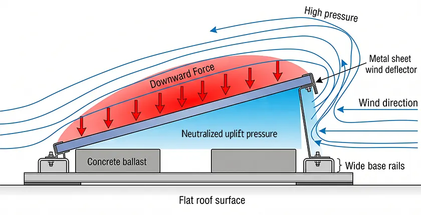
- Aerodynamics over mass: Wind deflectors manipulate boundary layer airflow to push the array down. Blindly adding concrete blocks overstresses the primary steel trusses.
- Polymer matching prevents tears: Thermal expansion and plasticizer migration destroy waterproofing. Isolate the aluminum chassis using slip sheets extruded from the exact same material as the roof.
- Corner uplift demands rigid splices: Building corners generate severe wind vortexes. Resist these localized forces by bolting structural splices to tie the outer arrays into the interior field.
- Point loads crush insulation: Narrow base rails punch through polyiso insulation under winter snow. Wide rails spread the array weight to prevent permanent deck craters.
- Specify solid ballast: Porous masonry blocks fracture during freeze-thaw cycles and shed sharp gravel. Demand solid ASTM C1491 concrete pavers seated in polymer trays.
Commercial flat roofs covered in TPO, EPDM, or PVC membranes protect high-value assets. They keep water out and secure the inventory below. Deploying a commercial solar array creates an engineering conflict. Mechanically anchoring the structure requires piercing the roof deck hundreds of times. Each penetration risks a leak, and roofing manufacturers void the warranty the moment a drill hits the membrane.
A flat roof solar ballast system secures the array using dead weight and aerodynamics, entirely avoiding physical penetrations. Engineering that non-penetrating footprint requires more than stacking concrete blocks until the aluminum racking stops moving. The layout demands precise calculations on fluid dynamics, structural load paths, and polymer friction limits.
Table of Contents
- 1. What Determines the Aerodynamic Stability of a Flat Roof Solar Ballast System?
- 2. How Do Slip Sheets and Base Rails Prevent Membrane Abrasion?
- 3. Wind Uplift Requirements Across Different Roof Zones
- 4. Calculating Roof Capacity: Dead Loads vs. Point Loads
- 5. Matching the Ballast System to Your Roof
- 6. Frequently Asked Questions
What Determines the Aerodynamic Stability of a Flat Roof Solar Ballast System?
Aerodynamic stability relies on boundary layer manipulation, not just static mass.
More concrete does not equal storm security. Relying solely on dead weight overstresses the primary steel trusses long before wind uplift tears the modules off. A ballast system resists uplift and lateral sliding through three interconnected mechanisms:
- System Dead Weight: The calculated mass of the solar modules, the aluminum racking chassis (main beams, columns, and structural splices), and the concrete ballast blocks.
- Aerodynamic Deflection: Wind deflectors installed on the rear face of the arrays alter the boundary layer. Instead of allowing wind to catch the underside of the modules, deflectors force high-velocity air over the top. The redirected airflow converts lateral wind pressure into a stabilizing downward force.
- Dynamic Coefficient of Friction: The mechanical grip between the base rails and the roof membrane. A dry TPO roof yields a friction coefficient around 0.5. When morning dew or winter ice covers the polymer, that grip drops abruptly to 0.1 or lower.
Reject static weight tables when evaluating system stability. ASCE 7-22 and SEAOC PV2 provisions mandate dynamic data derived from Boundary Layer Wind Tunnel Tests (BLWT). Adjust a wind deflector tilt by just 5 degrees, and you reduce the total concrete ballast requirement by up to 20%.
How Do Slip Sheets and Base Rails Prevent Membrane Abrasion?
Slip sheets and wide base rails isolate the racking from the roof membrane. You have a rigid metal structure sitting directly on a soft polymer. Two primary failure modes occur at this interface: abrasive friction and chemical cross-contamination.
Thermal expansion drives the friction. As morning sunlight hits the array, aluminum main beams heat up and expand. Over a 50-meter continuous row subjected to a 40°C daily temperature swing, the metal expands and contracts by approximately 46 millimeters. If bare aluminum or a generic rubber pad sits directly on a PVC or TPO roof, that daily micro-drag works like sandpaper. It eventually grinds through the waterproofing layer.
Chemical incompatibility causes the second failure. Place a generic EPDM pad on a PVC membrane under peak summer heat, and plasticizer migration begins. The roof membrane loses plasticizers and becomes brittle, while the rubber pad turns into a sticky adhesive. When the aluminum beam contracts 46 millimeters at night, the adhered pad tears the embrittled roof. You get a lateral tear and an interior leak.
The National Roofing Contractors Association (NRCA) guidelines mandate a chemically compatible barrier under load-bearing surfaces. Purpose-built slip sheets act as a sacrificial friction layer. They absorb the thermal displacement and block chemical cross-contamination.
Never use untested, off-the-shelf rubber pads on high-performance commercial membranes. Demand slip sheets extruded from the exact same polymer formulation as the underlying roof (e.g., TPO on TPO, PVC on PVC). Matching materials guarantee identical thermal expansion rates and completely eliminate plasticizer migration.
Wind Uplift Requirements Across Different Roof Zones
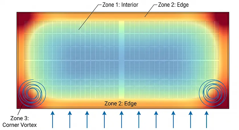
Figure X: Leading-edge airflow separation creates extreme uplift vortexes. Though single gusts impact only windward corners, ASCE 7 requires all four corners (Zone 3) to withstand this worst-case envelope.
Wind does not hit a flat roof evenly. Airflow separates at the building edge and rolls into uplift vortexes along the perimeters and corners. These vortexes divide the roof into three aerodynamic zones. A uniform ballast distribution plan across the entire field fails under localized pressure.
| Roof Zone | Wind Pressure Characteristics | Ballast & Interconnection Strategy |
|---|---|---|
| Zone 1: Interior | Lowest uplift and turbulence. Airflow reattaches to the surface. | Standard ballast block distribution. Minimum structural requirements for wind deflectors. |
| Zone 2: Edge | Moderate to high negative pressure. High risk of lateral sliding. | Increased ballast weight. Tighter spacing for module clamps and deflector fasteners. |
| Zone 3: Corner | Severe uplift forces. Extreme vortex generation during storm events. | Maximum concrete ballast combined with rigid mechanical interconnection of main beams to disperse localized uplift. |
In Zone 3, you hit a hard structural limit. Resisting corner uplift purely with extra concrete exceeds the localized deck capacity. The correct engineering practice involves bolting high-strength structural splices to tie the corner arrays back to the interior Zone 1 field. The interconnected metal chassis transfers and dissipates the uplift forces across a larger structural footprint.
Calculating Roof Capacity: Dead Loads vs. Point Loads
Structural capacity evaluations must clearly distinguish between distributed average dead load and localized point stress.
The total array weight divided by its footprint. Standard flat roof systems typically add 4 to 6 PSF (19 to 29 kg/m²) to the roof structure. That load keeps the primary steel trusses from yielding.
The concentrated pressure acting directly beneath the mounting base rails. A system can pass the average load check but still punch through the roof insulation. Narrow base rails exceed the 20 to 25 psi compressive strength of the Polyiso insulation boards.
When Polyiso crushes, the foam never bounces back. The compressed insulation leaves a permanent crater. Rainwater ponds in that depression, freezes, expands, and destroys the waterproofing over a few winters. Wide base rails spread the concrete ballast weight over a larger bearing area to reduce the compressive stress.
Calculating maximum point loads requires more than the racking dead weight. You must superimpose the worst-case winter snow load and the temporary live load of a maintenance crew walking the array. A system passing point load checks in July often crushes the roof insulation under 30 centimeters of wet January snow.
Matching the Ballast System to Your Roof
Ballast distribution is a function of membrane friction, structural limits, and wind uplift forces. Contact us with your project parameters and specific requirements, and we will engineer non-penetrating mounting layouts based on your local wind codes, building height, and membrane material.
Frequently Asked Questions
1.How does a non-penetrating ballast system accommodate roof drainage?
The layout requires strategic structural gaps. While aluminum main beams feature built-in water channels, real-world debris blocks the flow. Dust, leaves, and dirt wash down the standard roof slope (typically 1/4 inch per foot). If base rails sit continuously without interruption, the metal acts like a miniature dam. Industry standard practice requires leaving clear 12 to 18-inch gaps between rail segments. The open spaces allow debris to flush toward the scuppers and keep the array from becoming a retention pond.
2.What if the membrane needs replacement before the PV system?
Because the purlins hold zero mechanical anchors, the racking chassis remains entirely modular. Roofing contractors loosen the module clamps, remove the concrete ballast blocks, and temporarily slide entire rows out of the way. Once they lay down the new membrane and slip sheets, crews place the structure right back into position. You restore the roof without patching a single structural hole.
3.How does concrete ballast degradation impact the roof?
Porous CMU blocks fail under freeze-thaw cycles. They absorb moisture, which freezes, expands by 9%, and fractures the concrete from the inside. Spalling reduces the dead load required to resist aerodynamic uplift. Rainwater washes the abrasive aggregate across the roof deck. When technicians walk the array, their boots grind these jagged pieces through soft polymer membranes or scrape away protective coatings on bare concrete roofs.
Protect the roof asset through strict material specifications and physical isolation. You need solid concrete pavers meeting ASTM C1491 (minimum 3,000 PSI, maximum 5% water absorption). Seat the blocks inside UV-resistant polymer ballast pans rather than resting them on bare aluminum racking. If minor surface spalling occurs over the system lifespan, the pans contain the debris. The abrasive runoff never touches the waterproofing.
Here is a list of the sources used to create this article.
-
https://www.asce.org/publications-and-news/asce-7
-
https://www.scribd.com/document/388280596/CODE-Wind-Design-Solar-Panels
-
https://www.nrca.net/roofing-guidelines
-
https://codes.iccsafe.org/content/IBC2021P2/chapter-16-structural-design
-
https://www.polyiso.org/page/TechnicalBulletins
-
https://www.cement.org/learn/concrete-technology/durability/freeze-thaw-resistance
-
https://store.astm.org/c1491-14.html

Tao Chen
Marketing Director & IT Director · MIBET ENERGY
MIBET is a global designer and manufacturer of solar mounting systems. With over 10 years of professional experience, Tao Chen regularly contributes articles to our blog on structural design, installation, and maintenance, offering valuable guidance for navigating the complexities of solar projects.