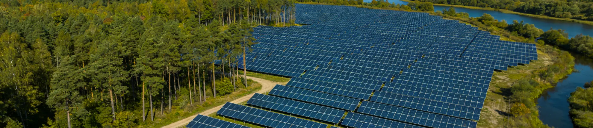
Foundation Types for Ground-Mount Solar Systems
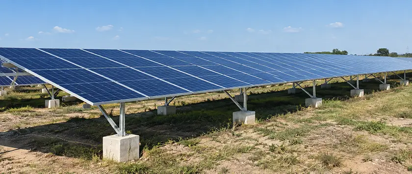
A ground-mount solar foundation has to satisfy two sets of conditions at once. Above grade it carries the structural loads from the array. Below grade it depends on whatever soil or rock the site provides. A pile section that installs cleanly across one property can run into shallow rock, a cemented layer, or a different corrosion environment at the next, and that one difference changes the installation method, the equipment, and the material take-off. Where early investigation misses that variation, the mismatch turns up later as refusal during installation, or as a foundation revision after the racking layout is already fixed.
Ground-mount solar systems are built on driven piles, ground screws, helical piles, concrete footings or piers, ballasted foundations, and site-specific solutions such as rock anchors. Selection comes down to soil and rock conditions, structural loads from the array, installation access, durability requirements, and the cost of the full construction sequence. Final foundation geometry remains project-specific, and where the design calls for it, trial installation or field load testing confirms the assumptions before production installation begins.
Table of Contents
Main Foundation Types for Ground-Mount Solar Systems
Ground-mount foundations differ mainly in how they transfer load from the post into the ground and how they are installed. Driven piles work through shaft friction and end bearing. Rotary foundations bear on helical or screw surfaces set into the surrounding soil. Concrete spreads load across a larger bearing area, and a drilled pier adds shaft resistance along its depth. Ballast holds position through its own weight and base friction, and rock anchors carry load into competent rock.
Driven Pile Foundations
Driven piles are steel members pushed or hammered into the soil with pile-driving equipment. Ground-mount structures use wide-flange sections, channels, or steel posts detailed for the racking system.
Below grade the pile resists compression and uplift through shaft friction and end bearing. Lateral load works differently. The soil around the upper part of the shaft pushes back as the pile deflects, and that reaction controls how far the post moves at grade and where the maximum bending moment develops. Lateral deflection and bending are especially sensitive to the stiffness of that near-surface soil.
Pile driving suits repetitive installation along long rows, where conditions stay consistent from one position to the next. Cobbles, cemented layers, buried obstructions, or shallow rock stop a pile before it reaches the specified depth.
Structural capacity and drivability are separate checks. A section can satisfy the service-load calculations and still be difficult to install across the site, because the pile also has to tolerate the stresses generated during driving.
Ground Screw Foundations
Ground screws install by rotation. Solar applications generally use tubular members with welded flighting of a defined pitch.
Compression and uplift both transfer through the embedded screw surfaces and the shaft, though each direction mobilizes the soil differently and has to be checked separately. Reaching the required depth depends on soil resistance, buried obstructions, and the torque available. Two limits apply, one set by what the machine can deliver and one by the torsional capacity of the shaft itself.
Helical Pile Foundations
A helical pile has a central steel shaft carrying one or more helical bearing plates and is installed by rotation. Section 202 of the International Building Code defines it the same way, and adds that each bearing plate is formed into a screw thread with a uniform defined pitch. The helices bear on the soil layer they are seated in, and shaft extensions carry them deeper where the design calls for it.
Ground screws and helical piles look much alike going into the ground, since both are installed by rotation. In this article, helical pile means a shaft with distinct helical bearing plates, and ground screw means the screw-shaped tubular foundations common in ground-mount racking. Commercial names vary by supplier and by market. Project documents are clearer when they state the geometry, the material, the installation criteria, and the basis used to establish capacity.
Concrete Foundations
Concrete foundations cover several forms. Ground-mount structures use cast-in-place footings, drilled piers, reinforced units with embedded posts or base plates, and precast elements where the project allows them.
A concrete footing suits a post base that needs a large bearing area on weak surface soil, or a connection that calls for a wider anchor-bolt pattern. Footing dimensions follow from the structural loads and the geotechnical data for that site.
Ballasted Foundations
Ballasted foundations hold the array in place with weight. Sliding resistance comes from the weight of the ballast acting through the friction available at the base, and overturning resistance from the restoring moment that same weight generates about the leading edge. Concrete blocks and similar arrangements are used on sites where penetration is restricted, such as capped landfills and other locations with a cap or liner that cannot be broken.
The soil beneath the ballast still carries the foundation loads. Bearing pressure and settlement govern how the block behaves in service, and sliding and overturning are checked against the design wind and snow loads. Drainage and erosion alter that support condition over time, since soil washed out from around a block, or softened underneath it, reduces the friction the sliding check assumed.
Ballast changes the way loads reach the ground. It does not remove the need for foundation design.
Rock Anchor Foundations
Shallow competent rock brings in drilled and grouted anchors. The crew drills into the rock, sets a steel bar or bolt in the hole, and grouts it so load passes from the anchor into the rock mass. Capacity can be governed by the steel section, the grout-to-rock bond, the bar-to-grout bond, or the rock mass itself. None of the bonded interfaces is open to inspection once the grout sets, so load testing is commonly specified where the design calls for field verification.
A large solar field can cross more than one geotechnical zone, so the same foundation method may not suit every row. Whatever the method, the structure needs an unbroken load path into soil or rock stiff and strong enough for the design loads.
Comparing Ground-Mount Solar Foundation Types
Site conditions do most of the narrowing before any sizing begins. Where the required embedment can be reached by penetration, driven piles and rotary steel foundations both stay in play. Restricted penetration moves the choice toward ballast, provided the surface can carry the resulting bearing pressure, while weak near-surface soil argues instead for a wider footing or a foundation that reaches a competent layer further down. Shallow competent rock calls for drilled and grouted anchors.
The table below is for early screening.
| Foundation Type | Installation Method | Where It Fits | Construction Sequence | Conditions to Check |
|---|---|---|---|---|
| Driven pile | Steel section driven into soil | Soil profiles where the required embedment can be reached by driving | Continuous mechanical installation along a row | Refusal, obstructions, rock depth, plumbness tolerance |
| Ground screw | Steel screw rotated into soil | Ground compatible with the screw geometry and the available torque | Rotary installation, little or no excavation | Soil compatibility, torque records, obstructions, required capacity |
| Helical pile | Shaft with helical bearing plates rotated into soil | Soil profiles with a bearing layer the helices can seat in | Rotary installation, with continuous special inspection where the adopted code requires it | Helix geometry, bearing layer depth, documented torque-capacity correlation where used |
| Concrete footing or pier | Excavated or drilled, reinforced, cast in place or precast | Sites needing a large bearing area or a wider anchor-bolt pattern at the post base | Placement and curing before structural assembly begins | Groundwater, concrete delivery, curing time, site access |
| Ballasted foundation | Foundation mass placed on prepared ground, no penetration | Areas with penetration restrictions, where the surface can take the bearing pressure | Material handling and ground preparation dominate | Sliding, overturning, bearing pressure, settlement, drainage |
| Rock anchor | Drilled into rock and grouted | Shallow competent rock or other defined subsurface conditions | Drilling, grouting, and proof testing added to the sequence | Rock quality, drilling conditions, grout details, proof test criteria |
The table narrows the choice, though final sizing still comes from the foundation geometry, the site conditions, the structural loads, and the construction method.
Material price is only one part of installed foundation cost. Mobilization, predrilling, concrete work, testing, and the number of foundations a crew completes per shift all feed into it, and two options with quite different component prices can end up close together once the whole sequence is priced.
Soil and Site Conditions That Drive Foundation Selection
The ground surface says very little about what a foundation crosses below grade. Soft soil overlies dense material. Rock rises close to grade in one corner of a site and drops away a short distance later, and groundwater and soil chemistry shift across the same property. Each condition has a physical consequence for the foundation.
| Site Condition | Effect on Foundation Planning |
|---|---|
| Soft or loose soil | May push the required resistance deeper, or call for a wider bearing area or ground improvement |
| Dense or cemented layers | Add capacity once the foundation reaches them, and resist driving or rotary advance on the way down |
| Cobbles and boulders | Deflect the pile tip off line, obstruct rotary flighting, or stop penetration outright |
| Shallow bedrock | Limits embedment and brings drilling, anchoring, or a local foundation change into play |
| Expansive clay | Swells and shrinks with seasonal moisture, loading the shaft in uplift and moving the structure above it |
| High groundwater or persistently wet soil | Affects excavation method, soil response during installation, and corrosion around buried steel |
| Frost-prone ground | Produces seasonal heave and adfreeze uplift on embedded members |
| Sloping or erosion-prone terrain | Changes equipment access, exposed post length, drainage paths, and scour around the foundation |
| Corrosive soil | Increases buried-steel section loss and drives the protection specified |
| Placed fill and backfill | Changes the oxygen exposure around buried steel, and with it the corrosion assessment that applies |
Rock, Cobbles, and Installation Refusal
For a driven pile, refusal is the point where the pile stops advancing under the specified driving conditions. In practice the project's driving criteria define it with a number, usually a blow count over a set penetration, so the crew and the inspector work from the same threshold.
The pile head stands above its intended cut-off elevation once driving reaches that limit, and the exposed post height across that section of the array no longer matches the rest. Predrilling, a different pile section, or a local change of foundation type then come into consideration, once the subsurface condition is understood.
Frost, Drainage, and Foundation Movement
Frost acts on embedded members through two mechanisms. Frost-susceptible soil takes up water and forms ice lenses that lift the ground. At the same time, the frozen soil bonds to the steel surface of the shaft. That bond, known as adfreeze, drags the pile up with the heaving soil.
Where the anchorage below the frost zone cannot resist that uplift, the pile rises with the ground and settles only partway on thawing, and the displacement accumulates over successive winters. Applicable codes require frost protection, often through a minimum foundation depth below the local frost line, though other approved methods exist.
Surface runoff moves soil away from around a pile or a ballast block, and the soil level assumed in the calculation goes with it. For a post, the cantilever above grade grows and the embedded length below it shrinks. The same wind load then produces a larger moment at grade, with less soil left to resist it.
Soil Corrosivity
Buried steel stays in contact with the soil for the whole service life of the structure. Oxygen availability shapes how much of it corrodes as much as soil chemistry does, and a standard corrosion assessment can miss that.
The National Bureau of Standards inspected steel piles that had been in service for decades across a range of sites. Piles driven into undisturbed natural soil showed corrosion too slight to affect strength or service life, and the soil corrosivity indices developed for buried pipe did not predict that behavior.
Undisturbed ground a short distance below grade holds too little oxygen for the reaction to proceed at a meaningful rate.
Piles in fill and near the water table showed more variable loss. Backfill lets oxygen reach the steel and allows differential aeration cells to form along the shaft.
pH, resistivity, chlorides, and sulfates carry more weight in placed fill than in native ground.
The same aeration difference applies at the ground line, where the shaft passes between soil and atmosphere and section loss tends to concentrate in a band rather than spread along the shaft.
Grading creates both cut and fill zones, and the two are not equivalent below grade. A foundation in placed fill meets a different soil profile and a different corrosion environment from one driven into undisturbed ground. For your project, the geotechnical report needs to show whether the corrosion samples represent native soil or placed fill, and the foundation layout is worth checking against the cut-and-fill plan.
What Determines the Right Foundation for a Solar Project?
Soil conditions narrow the available options. The structure above then sets what each foundation has to resist, while exposure, design life, and local codes add requirements of their own.
Structural Loads
Under wind, a solar foundation carries compression, uplift, lateral force, and bending at the same time. Wind pressure acts on the module surface, and the resulting forces travel down through the rails or purlins, the beams, the posts, and the foundation connection. Snow and seismic actions add governing load cases of their own where they apply.
- Module surface
- Rails or purlins
- Beams
- Posts
- Foundation connection
A change above ground shows up below it. PV table width, tilt, ground clearance, and post spacing all move the reactions at each foundation.
For projects in the United States, ASCE/SEI 7-22 sets the environmental loading criteria. The 2022 edition added wind provisions written specifically for fixed-tilt ground-mounted arrays, a case earlier editions left to engineering judgment. Single-axis trackers fall outside those provisions, and ASCE/SEI 49 covers the wind tunnel route instead, listing ground-mounted solar trackers among its applications.
Confirm which edition your jurisdiction has adopted before the load calculations begin.
Wind speed maps and pressure coefficients are calibrated together within an edition, so provisions from different editions cannot be mixed.
Mounting Structure and Array Configuration
Fixed-tilt structures and trackers draw on the same foundation technologies, and the calculations behind them are specific to the structure above. A fixed-tilt table transfers load through a rigid geometry. A tracker adds a torque tube, bearings, drive components, and a row that rotates through the day.
Every pile along the row has to land within the position and plumb tolerance the tracker allows, because the bearings have to hold the torque tube on a single axis. Most trackers carry some adjustment at the post and bearing interface, and the permitted offset depends on the design. A pile outside that range leaves its bearing misaligned with the ones on either side, and the tube binds as it rotates, so the wear shows up in the bearings and drive components while the pile that caused it stays within its own structural limits.
Decommissioning and Site Restoration
Decommissioning comes last in the project and still affects the foundation chosen at the start. A steel pile or screw can often be extracted mechanically, leaving the ground close to its original condition. A concrete pier may need excavation and breaking out, or it may stay in place where the lease permits. Where the land agreement requires site restoration, removal cost becomes part of the lifecycle comparison.
Ground-Mount Solar Racking and Foundation Design
Mibet designs ground-mount solar racking with the foundation treated as part of the same structure. Working from your site conditions, array layout, design loads, and available geotechnical information, we recommend the foundation types that suit the site, carry them into the mounting design, and issue the layout drawings and bill of materials that go with the proposal.
Send us your site details and design requirements, and we will come back with a ground-mount racking and foundation proposal.
Frequently Asked Questions
1. How deep do ground-mount solar piles need to be?
There is no standard embedment depth. The required depth comes from the soil profile, the pile geometry, the foundation reactions, the installation conditions, and the verification criteria the project sets.
Any early depth figure rests on an assumed soil profile, an assumed design wind speed, and a specific pile section. A change in any of those inputs changes the embedment it supports.
2. Are ground screws and helical piles the same?
Not always. Section 202 of the International Building Code defines a helical pile as a steel shaft carrying one or more helical bearing plates, with each plate formed into a screw thread of a uniform defined pitch.
Ground screw is the broader commercial term, applied across the solar market to a range of screw-shaped steel foundations that install by rotation. The project specification is what defines the geometry, the material, the installation criteria, and the performance required.
3. Can a ground-mount solar system be installed without penetrating the soil?
Yes. Ballasted ground-mount structures work where conventional pile penetration is restricted, such as capped landfills and sites with a liner that cannot be broken.
The ballast still needs checking for sliding, overturning, bearing pressure, settlement, and drainage, along with the environmental loads for the site. The design still has to cover the structural and geotechnical checks that apply to a ballasted foundation.
4. Do ground-mount solar foundations require pull-out testing?
That depends on the project. Foundation type, soil conditions, the project specification, and the responsible engineers decide whether pull-out or other load testing is required.
ASTM D3689/D3689M covers static axial tensile testing of deep foundation elements. The project sets the test loads, the number and location of tests, the procedure, and the acceptance criteria. It also decides what the test is for. A proof test loaded to a multiple of the design load answers a different question from one taken to a failure criterion.
Here is a list of the sources used to create this article.
- International Building Code, Section 202: Helical Pile. ICC, 2021.
- Romanoff, M. Corrosion of Steel Pilings in Soils. NBS Monograph 58, 1962.
- ASCE/SEI 7-22, Minimum Design Loads and Associated Criteria for Buildings and Other Structures.
- ASCE/SEI 49-21, Wind Tunnel Testing for Buildings and Other Structures.
- ASTM D3689/D3689M-25, Standard Test Methods for Deep Foundation Elements Under Static Axial Tensile Load.

Tao Chen
Marketing Director & IT Director · MIBET ENERGY
MIBET is a global designer and manufacturer of solar mounting systems. With over 10 years of professional experience, Tao Chen regularly contributes articles to our blog on structural design, installation, and maintenance, offering valuable guidance for navigating the complexities of solar projects.