
Non-Penetrating Klip-Lok Solar Mounting Clips
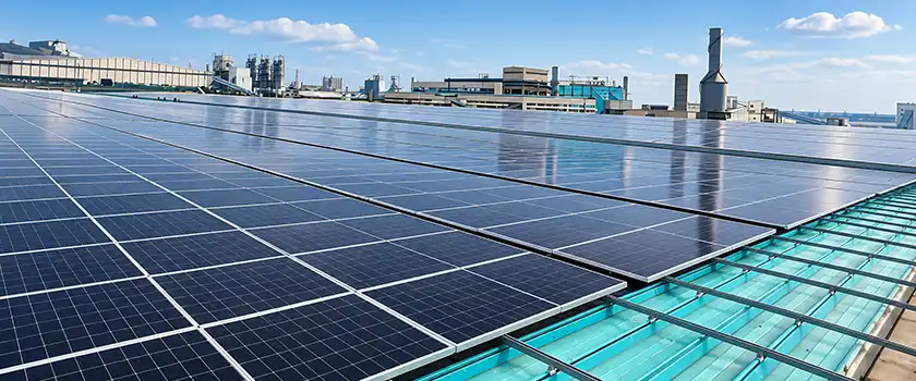
On a Klip-Lok roof, the array layout and attachment method need to be planned together. Lysaght describes Klip-Lok as concealed-fix cladding, with no exposed fasteners and no piercings through the sheet. With no existing attachment point to reuse, a non-penetrating attachment has to take its grip from the sheet itself, usually at a rib. That thin steel rib then becomes part of the load path into the building structure.
Non-penetrating Klip-Lok solar mounting clips grip the ribs of a Klip-Lok concealed-fix roof and give PV rails or module clamps an attachment point without drilling through the sheet. Wind uplift and sliding loads pass from the clip into the sheet, then through the hidden roof clips to the purlins. A clip's capacity and permitted spacing apply only to the roof profile, sheet thickness and array type they were assessed for. The exact roof profile, such as Klip-Lok 406 or 700 Hi-Strength, is the first thing to confirm.
Table of Contents
- How Non-Penetrating Klip-Lok Solar Mounting Clips Work
- Which Klip-Lok Roof Profiles Are Compatible?
- Klip-Lok Solar Clamp Specifications and Materials
- Rail-Based, Rail-Less and Tilted Mounting Options
- Load Capacity and Structural Checks
- Waterproofing, Roof Warranty and Corrosion
- Installing Klip-Lok Mounting Clips
- Get a Klip-Lok Solar Mounting Proposal for Your Roof
- Frequently Asked Questions
How Non-Penetrating Klip-Lok Solar Mounting Clips Work
Klip-Lok is a family of concealed-fix steel roof profiles from Lysaght, part of BlueScope. Each sheet is held to the purlins by hidden roof clips, and no fastener passes through the sheet.
A non-penetrating solar clip clamps onto the sheet ribs from above. The lower part of the clip body closes around a rib and is tightened onto it, and the upper part carries an L-foot and rail, a module clamp, or an adjustable tilt leg. The same part is also sold as a Klip-Lok solar clamp or mounting bracket.
The load path runs from the modules down to the purlins:
- PV modules
- Racking
- Solar clip
- Sheet rib
- Roof clips
- Purlins
Non-penetrating means no hole is made in the sheet. The array still depends on the roof to carry every load.
The attachment method follows the cladding type. On pierce-fixed cladding such as corrugated sheet, mounting feet are fastened through the sheet into the structure, with a seal at each fastener. Klip-Lok sheet has no fasteners through it, and a rib clip keeps it that way. Removing the array later leaves no holes to seal.
Which Klip-Lok Roof Profiles Are Compatible?
Mibet makes two Klip-Lok clip models. One fits 406 mm and 410 mm profiles, the other 700 mm profiles. Together they cover the three Lysaght profiles below and comparable concealed-fix sheets from other manufacturers: Fielders KingKlip 700, Stramit Speed Deck Ultra, and Safintra Saflok 410 and 700.
| Roof profile | Nominal cover width | Nominal rib height | Clip model |
|---|---|---|---|
| Klip-Lok 406 | 406 mm | 41 mm | 406 |
| Klip-Lok 700 Classic | 700 mm | 40 mm | 700 |
| Klip-Lok 700 Hi-Strength | 700 mm | 43 mm | 700 |
Profile dimensions: Lysaght KLIP-LOK product information.
Cover width alone does not identify a roof. The two 700 mm Klip-Lok profiles differ by 3 mm in rib height and in rib shape, and other manufacturers' sheets of the same width have rib shapes of their own. The 700 clip is listed for each 700 mm profile named above. Checking any other sheet takes the full profile name or, if your roof drawings do not give one, a measured rib cross-section and a photo of the sheet end.
After the profile, sheet thickness is the next thing to confirm. Base metal thickness (BMT) is the thickness of the steel before coatings are applied. In Australia, Klip-Lok sheet is commonly supplied in 0.42 mm or 0.48 mm BMT, depending on the profile. On the same profile, thinner sheet has less capacity at the rib. It helps to have your roof's BMT on hand when you select clips.
Klip-Lok Solar Clamp Specifications and Materials
Mibet's Klip-Lok clamps pair an AL6005-T5 aluminum body, an extrusion alloy also common in PV rails, with SUS304 stainless steel bolts that resist corrosion and need no protective plating. EPDM pads line the jaws and bear against the roof coating.
| Item | Specification |
|---|---|
| Models | Two: one for 406 mm and 410 mm profiles, one for 700 mm profiles |
| Attachment to sheet | Clamps onto a sheet rib, with no holes in the sheet |
| Clip body | AL6005-T5 aluminum alloy |
| Fasteners | SUS304 stainless steel |
| Contact pads | EPDM rubber |
| Top connection | M8 threaded interface for an L-foot and rail, a module clamp, or an adjustable tilt leg |
| Array types | Flush or tilted, rail-based or rail-less |
| Product warranty | 10 years |
Rail-Based, Rail-Less and Tilted Mounting Options
Rails, module clamps or tilt legs connect to the clip, depending on the array layout.
| Layout | How the modules connect | What to check |
|---|---|---|
| Flush, rail-based | An L-foot on each clip carries an aluminum rail, and module clamps secure the modules to the rails | Rail span between clips |
| Flush, rail-less | Mid and end clamps secure the module frames directly to the clips | Rib positions against the module's permitted clamping zones |
| Tilted | Adjustable tilt legs on the clips set the modules at a steeper angle than the roof pitch | Wind load at the chosen tilt angle, and the loads at each leg |
A rail-less layout saves you the cost and weight of rails, but the modules can then be clamped only at rib positions. Module manufacturers define the zones of the frame that may be clamped, and the rib positions come from the roof profile. Where the ribs do not line up with a permitted clamping zone, the layout needs rails or a different module orientation.
A tilted layout needs its own wind design at the chosen tilt angle and height. Tilting generally raises the wind load on the array, and the tilt-leg connections become part of the load path.
Load Capacity and Structural Checks
The clip is one link in the load path, and the weakest link governs.
| Link in the load path | Governed by | What changes it |
|---|---|---|
| Wind action on the array | AS/NZS 1170.2:2021 | Wind region, terrain, building height, roof zone, array tilt and position |
| Rails | Rail section and span | Module size, clip spacing |
| Solar clip on the rib | Clip design, verified by testing and certification | Roof profile, BMT, loading direction |
| Sheet and roof clips | Roof manufacturer's capacity data and AS 1562.1:2018, checked for the point loads at the clips | BMT, support spacing, clip positions |
| Purlins and structure | Structural design of the building | Member size, spacing, condition |
Engineers calculate the wind load on the array under AS/NZS 1170.2:2021, and for flush arrays its Appendix B can call for closer clip spacing in edge and corner zones than in the middle of the roof. Clip spacing therefore varies by roof zone, and a single spacing value rarely applies to the whole roof.
Testing and engineering certification cover the clip system. A certificate typically identifies the wind region, terrain category, roof profile and BMT, together with the permitted clip spacing. If your project falls outside that scope, it needs site-specific engineering.
Array loads also pass through the roof sheets, roof clips and purlins. Before the layout is finalized, your structural engineer needs to verify that these have the capacity for the array's dead load and the added wind load. A clip certificate does not replace that check. Additional clips reduce the load at each connection when the sheet is the limit. Where the purlins govern, the options are to keep panels out of the highest-load zones or to strengthen the roof.
Waterproofing, Roof Warranty and Corrosion
A rib clip leaves the sheet unpierced and bears on the coated rib. Clip fit and contact materials affect weathertightness, corrosion protection and roof warranty conditions.
Waterproofing and Sheet Movement
Klip-Lok's weathertightness comes from a sheet with no piercings and from ribs that rise above the flat pans carrying the water. A rib clip changes neither, as long as it is tightened to the specified torque and the rib keeps its shape.
The solar clip attaches only to the sheet. As the steel expands and contracts with temperature, the clip moves with it, and the roof clips below still allow that thermal movement.
Roof Warranty
BlueScope warrants the steel in certain applications, subject to conditions on how the roof is installed and maintained. For a solar array, the relevant conditions concern which materials touch the sheet and whether the sheet under the panels can still be washed and inspected. If your roof is already under warranty, check the steel warranty document and any separate installer's warranty.
Corrosion at the Contact Points
On a rib clip, the body, the pads and the fastener ends can each bear on the coated surface. What touches the coating matters, because two different metals in contact, with moisture between them, set up galvanic corrosion.
BlueScope's Technical Bulletin TB-36 advises against dissimilar metals in direct contact with COLORBOND (pre-painted) or ZINCALUME (metallic-coated) steel roofing. The BlueScope compatibility table lists aluminum as suitable for both finishes. EPDM pads cover the jaws, and the aluminum body is a compatible metal.
Panels keep rain off the sheet beneath them, and contaminants collect where the sheet goes unwashed. TB-36 recommends a clearance commonly greater than about 75 mm, measured from the top of the rib to the underside of the panels. That gap gives access for cleaning and inspection. On a flush array, the height of the clip and the parts above it set this clearance at the design stage.
Installing Klip-Lok Mounting Clips
Fitting the clips takes a torque wrench and standard hand tools.
- On site, confirm that the roof profile and BMT match the array design and the supplied clip model.
- Mark the clip positions from the array design, including any closer spacing in edge and corner zones. For rail-based arrays, mark the rail lines as well.
- Fit each clip onto its rib with the pads seated, and tighten the side bolts with a torque wrench to the value given in the installation instructions.
- Check that each clip is fully seated on the rib and that the coating has not been scratched.
- Attach the L-feet and rails, the module clamps, or the tilt legs, then mount the modules.
Overtightening can deform the rib wall, particularly on thinner sheet. Under-torquing lowers the clamping force, and with it the clip's slip resistance along the rib.
Get a Klip-Lok Solar Mounting Proposal for Your Roof
A proposal starts from the following roof and project details:
- Roof profile name and BMT, plus a rib cross-section and photo where the profile is not identified
- Purlin spacing and the condition of the sheets and roof clips
- Project location, plus wind region and terrain category if known
- Building length, width and height, roof pitch and where the array sits on the roof
- Module model and dimensions, and the array type: flush or tilted with the tilt angle, rail-based or rail-less
Mibet manufactures solar mounting clips for Klip-Lok roofs, along with the matching L-feet, rails and tilt legs. Send the details above through the contact page. Our engineering team will calculate clip spacing for each roof zone and provide a proposed layout drawing, bill of materials and quotation. Your structural engineer can then review the layout.
Frequently Asked Questions
1. Are klip-lok roof fixing clips the same as solar mounting clips?
No. Roof fixing clips are part of the roofing system and hold each Klip-Lok sheet to the purlins from underneath. Solar mounting clips are separate parts that clamp onto the sheet ribs from above and carry the PV racking. Array loads transfer from the solar clip into the sheet and then through the roof fixing clips.
2. Is an older klip-lok roof suitable for solar mounting clips?
Yes, provided the rib matches a listed profile and the sheets, roof clips and purlins are in sound condition. A clip takes its grip from the rib, and the load then passes through the sheet to the roof clips and purlins. Corrosion, damage or loose fasteners anywhere along that path reduce what your roof can carry. Have the roof inspected before the array is designed, and have a structural engineer review the findings.
3. How many klip-lok clamps does an array need?
There is no fixed number of clamps per module or per kilowatt. The number depends on the clip spacing the wind design allows, and that spacing varies with the site, the building and the roof zone. Edge and corner zones usually need closer spacing than the middle of the roof.
4. Do klip-lok clips fit standing seam roofs?
No. Klip-Lok clips are shaped for the ribs of concealed-fix profiles. Standing seam roofs, whether snap-lock or mechanically seamed, use seam clamps that grip the raised seam.
5. Can the clips be used outside australia?
Yes, if the local roof profile is compatible. Comparable concealed-fix sheets are rolled elsewhere, such as Saflok in South Africa. Fit is confirmed against the local profile drawing, and wind design follows the local wind standard. A certificate written for Australian conditions does not carry over to another market.
Sources used for this article are listed below. Check the current edition of each document before using it on a project.
Klip-Lok, COLORBOND, ZINCALUME and the other profile names are trademarks of their respective owners. Mibet is not affiliated with these owners, and the names are used only to describe roof compatibility.

Tao Chen
Marketing Director & IT Director · MIBET ENERGY
MIBET is a global designer and manufacturer of solar mounting systems. With over 10 years of professional experience, Tao Chen regularly contributes articles to our blog on structural design, installation, and maintenance, offering valuable guidance for navigating the complexities of solar projects.