
Commercial Rooftop Solar Mounting System Selection Guide
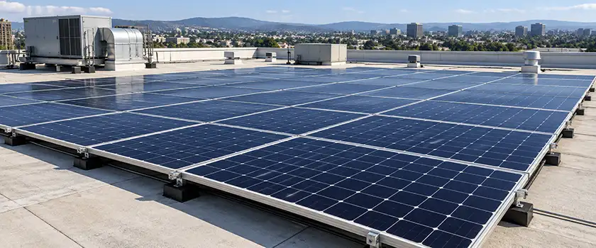
A commercial building has been chosen for rooftop solar and the array size is roughly set. Your next decision is how that array will be secured to the roof. That choice determines the loads the building has to carry and the engineering documents needed for approval, and it can change whether the roof warranty still applies. Arrays connect to metal, membrane and concrete roofs in different ways, and wind loads vary from the edge of a roof to its center.
The right commercial rooftop solar mounting system depends mainly on the roof covering, the capacity of the structure beneath it, and the site's wind and snow loads. The covering and structure decide whether ballast, mechanical attachment or seam clamps are viable. Wind and snow then determine how the rooftop solar mounting structure is configured across the roof. Those loads, the layout and approval requirements can still change the choice, so the selection cannot be finalized until the roof data and the governing code are confirmed.
Table of Contents
- What Determines the Right Mounting System for a Commercial Roof?
- How Roof Type and Condition Narrow the Options
- Wind, Snow and Roof Zones Set Attachment Spacing and Ballast
- Ballasted, Mechanically Attached and Seam-Clamped Systems Compared
- Which Array Layout Fits a Commercial Roof?
- Documents That Support Structural Approval
- Get a Solar Mounting Proposal for Your Commercial Roof
- Frequently Asked Questions
What Determines the Right Mounting System for a Commercial Roof?
Roof covering, structural capacity and the site's wind and snow loads largely decide the choice. They narrow the available connection methods and array layouts.
In this guide, the mounting system means everything between the module frame and the building. The rooftop solar mounting structure carries the modules on module clamps and rails, with main beams and columns added in elevated frames. The roof connections hold it in place through flashed attachments, seam clamps or ballast trays.
- Roof covering and condition. Standing seam, trapezoidal or corrugated metal roofs, membrane roofs and concrete decks each allow different connection methods.
- Structural capacity. The structure under the covering limits how much added load the roof can take, and where.
- Wind, snow and roof zones. Site conditions set the loads on the array and how those loads vary across the roof.
- Connection method and roof interface. Ballast, mechanical attachment, seam clamps and hybrid systems resist the loads in different ways and affect waterproofing and drainage differently.
- Array layout. Flush, tilted, east-west and elevated frame layouts change the load path and the roof area used.
- Approval requirements. The certifications and calculations needed for approval can rule out a product or layout, so they are worth confirming early.
Wind loads, connection method and layout are worked out together, often in more than one pass. The layout changes the wind loads, and the attachment spacing or ballast that results can force a change in the layout.
How Roof Type and Condition Narrow the Options
The roof covering and the structure beneath it are checked together. An attachment that suits the covering is ruled out if the roof cannot carry the added load.
Roof Covering and Attachment Compatibility
The clamp is where the load enters a standing seam roof. Its holding strength varies with seam profile, panel material, gauge and load direction. Ask the clamp supplier for allowable loads backed by tests on your seam profile, in both the uplift and parallel-to-seam directions.
Trapezoidal and corrugated roofs typically take fasteners through the ribs, each one sealed against water. Purlin-fixed attachments transfer load into the building frame. Sheet-fixed attachments rely on the roof sheet and its existing fasteners, and each type needs its own spacing and capacity checks. A roof photograph identifies the profile type, but finalizing the attachment grid needs a dimensioned profile drawing, the sheet thickness and the purlin spacing.
On a membrane roof, the choice between ballast and flashed attachments comes down to the roof assembly beneath the membrane and what the roofing manufacturer will accept. Mechanical attachments add flashed penetrations to the roof. The installer agrees on the flashing detail with the roofing manufacturer beforehand, and the manufacturer may inspect the finished work to confirm that the warranty remains valid. Ballasted bases sit on a protection pad or slip sheet, a layer the roofing warranty may require.
Ballast is a common solution on concrete decks, which normally carry a membrane or other waterproofing layer. Where wind uplift is high or the slab cannot take the ballast weight, post-installed expansion or adhesive anchors can hold the array down mechanically, provided the slab has enough thickness and sound concrete for the anchor embedment. In a post-tensioned slab, the tendons have to be located before any drilling. Because the anchors penetrate the waterproofing, the anchor design and the sealing detail are worked out together.
Structural Capacity and Roof Condition
Structural capacity governs whether a connection method can be used at all. Wind and snow loads on the modules pass through the clamps, rails or frames and roof connections into the purlin, rafter or deck, and finally into the primary structure. The same members carry the self-weight of the racking and any ballast. The roof sheet or membrane is rarely the final support.
- Modules
- Module clamps
- Rails or frames
- Roof connections
- Purlin, rafter or deck
- Primary structure
The roof structure has to carry the full dead load of the modules, racking and ballast, including the concentrated loads from support frames. Where the 2024 International Building Code (IBC) applies, Chapter 16 sets that requirement and also requires the PV dead load to be shown on the construction documents. In practice, your structural engineer needs the mounting supplier's weights and support reactions, including uplift, to complete that design check.
A 2018 guide from the US National Renewable Energy Laboratory (NREL) gives typical added weights for rooftop PV. Attached arrays typically add less than 3 pounds per square foot (psf) of collector area, about 0.14 kPa. Ballasted arrays add 3 to 8 psf (0.14 to 0.38 kPa), depending on tilt and wind loading. The wind design for your site sets the actual ballast. Is a roof that can carry the average weight adequate? Only if no single purlin or column base is overloaded.
Existing conditions belong in the same review. They include the original design loads and remaining spare capacity, purlin spacing and condition, rooftop equipment and any gravel ballast already on the roof. Gravel uses up part of that capacity. If the roof is near the end of its service life, it is better replaced before the array goes on. If the drawings are missing, the structural engineer has to establish the capacity from a site survey and calculations.
Wind, Snow and Roof Zones Set Attachment Spacing and Ballast
Wind sets how closely the attachments are spaced or how much ballast the array needs. It does not load a roof evenly. Airflow separates at the roof edges and corners and produces stronger suction there than over the rest of the roof. The exposed edges of the array also take higher wind loads than its interior rows. The result is a zone map for the rooftop mounting structure, with closer attachment spacing or more ballast in the perimeter and corner zones and wider spacing or less ballast in the interior.
The wind check does not stop at the mounting structure. A roof-mounted array transfers wind load into the building beneath it, and the roof structure has to be checked for that load.
Wind-loading standards vary by market. In the US, wind loads on rooftop arrays are calculated under the solar provisions in Chapter 29 of ASCE 7. The 2024 IBC references the 2022 edition, ASCE 7-22. European projects use EN 1991-1-4 together with the National Annex for the relevant country.
In the US, confirm which edition the authority having jurisdiction (AHJ) has adopted before the design loads are calculated. In every market, the mounting documents have to match the standard and edition in force at the site.
Snow adds gravity load, and drifting against the array, parapets or rooftop equipment can concentrate it locally. On a ballasted roof, snow and ballast draw on the same spare capacity. Snow drifts do not follow the wind zones, so they are checked separately.
Ballasted, Mechanically Attached and Seam-Clamped Systems Compared
Ballast holds the array down with weight, mechanical attachment fastens it to the roof, and seam clamps grip a standing seam roof. The right one depends on spare capacity, wind uplift and the roof covering, and each comes with its own trade-off in weight and labor.
| Connection method | What resists uplift | Effect on the roof | Project trade-off |
|---|---|---|---|
| Ballasted | Weight of the modules, racking and ballast, with uplift shared between supports where the racking is interconnected | Added dead load across the array, usually heavier toward the perimeter, and no new penetrations in the roof covering | No flashing work, but more weight to ship, hoist and place, with the amount set by the wind design |
| Mechanically attached | Fasteners or anchors fixed into the roof sheet, deck or framing | Lower added dead load, concentrated at each attachment, plus penetrations that need sealing or flashing | Less weight to handle, more labor per attachment and coordination with the roofing contractor |
| Seam clamped | Clamp grip on the seam, then the roof panel and its clips into the structure | Array load carried through the standing seam roof panels, with no penetrations in the panels | No sealing work, but each seam profile needs its own clamp data |
Hybrid systems combine ballast and mechanical attachment, with roof anchors added where more resistance is needed. They are lighter than a fully ballasted array, though the anchors need flashing.
Where fasteners or anchors penetrate the roof, the connection has two functions. The fastener and the sheet, deck or purlin it is fixed into carry the structural load, while the flashing, seal or gasket keeps water out. The two are detailed together but checked separately. A watertight attachment can still be too weak, and a strong one can still leak.
An unattached ballasted array is held in place only by weight and friction. In seismic regions where ASCE 7-22 applies, Section 13.6.12 sets the conditions for such arrays, including height limits for the building and the array, a maximum roof slope and clearance for seismic displacement. The layout has to provide that clearance at roof edges, parapets and rooftop equipment.
The table below shows the usual starting point for common roof and site conditions.
| Roof and site condition | Usual starting point | What can change it |
|---|---|---|
| Low-slope membrane (TPO, PVC, EPDM, bituminous) or concrete roof with documented spare capacity and moderate wind exposure | Ballasted | Roofing manufacturer's requirements, insulation bearing capacity, drainage layout, clearance for seismic displacement |
| Low-slope membrane or concrete roof with limited spare capacity, or high wind uplift at the perimeter | Mechanically attached or hybrid | Limits on penetrations, flashing details accepted by the roofing manufacturer |
| Standing seam metal roof | Seam clamps | Clamp test data for the profile, capacity of the roof panels and clips |
| Trapezoidal or corrugated metal roof | Mechanically attached with rails or short rails | Whether fasteners reach purlins, sheet thickness and condition |
That starting point is provisional, and the zone map and the capacity check can change it. A ballasted design may become mechanically attached or hybrid when the perimeter ballast turns out to exceed the roof's spare capacity.
Which Array Layout Fits a Commercial Roof?
Flush layouts are the usual choice on metal roofs, and single-tilt or east-west layouts on low-slope membrane and concrete roofs. Elevated frames are for roofs where the space below has to stay usable or support points are few. The module's installation manual specifies the permitted clamping zones, and a change of module model means rechecking rail spacing and clamp positions.
On low-slope roofs, tilted layouts bring row spacing into the design. In an equator-facing single-tilt array, the gaps between rows limit shading but reduce roof coverage. An east-west array places rows back to back and needs far less space between them. More modules fit on the same roof area, though each usually produces less energy than an equator-facing module. Tilt angle and row spacing calculations are a separate design exercise.
Elevated frames carry the array on columns and main beams, keeping the space below usable and transferring the load to selected roof members. Wind on a raised, tilted array creates an overturning moment at the supports and concentrates the reactions at the column bases. The ASCE 7-22 provisions for tilted rooftop arrays (Section 29.4.3) apply only within set limits on roof slope, tilt, panel length and height. The top edge of the modules can be no more than 4 ft (1.2 m) above the roof. Frames outside those limits need a project-specific wind analysis.
Documents That Support Structural Approval
The documents a project needs vary with the market and the design method. Each covers a different part of the approval, from product performance to the capacity of the existing roof.
| Document | What it establishes | What it does not cover |
|---|---|---|
| UL 2703 listing (US) | Functions stated in the listing: mechanical loading, bonding and grounding, fire classification or a combination, for the specified racking and modules | Project-specific structural analysis and any function outside the listing's stated scope. Roof attachments and flashing are outside the standard's scope |
| Structural calculation package | Wind, snow and seismic loads on the array and supports, attachment spacing or ballast quantities and support reactions | The capacity of the existing building, unless that check is part of its scope |
| Wind tunnel report | Pressure coefficients for the tested array layout, tilt and height, for use with the stated code edition | Layouts, roof zones or code editions outside the report |
| Structural assessment of the existing roof | Whether the roof can carry the added loads | The strength of the mounting system itself |
The local building authority decides what has to be submitted, and the project's engineer of record determines the analysis needed to support it. In the US, whether a licensed engineer's stamp is required depends on state licensing rules, the AHJ and the project scope. You can review product certifications early in the selection. Final project calculations have to wait for the confirmed layout.
Get a Solar Mounting Proposal for Your Commercial Roof
Mibet supplies rooftop solar mounting structures for metal, membrane and concrete commercial roofs. Send us the project location, roof drawings or photographs, the module model and the planned array size. The proposal covers a recommended mounting approach and a budget estimate.
Once the roof data and design loads are confirmed, the Mibet engineering team sets attachment spacing or ballast by roof zone. Your structural engineer can then check that layout against the building's capacity before you order.
Frequently Asked Questions
1. Can the same commercial rooftop mounting system be used in different countries?
Rails and clamps often can, but roof attachments, certifications and calculations have to be checked against local requirements. Test data may carry over, while the project calculations are redone for the local code and the site's design loads.
2. Does the connection method affect the roof warranty?
It can. The roofing manufacturer sets the warranty terms for each roof assembly. Ask for written confirmation that the proposed ballast, attachments or seam clamps are acceptable for your roof.
3. How much of a commercial roof can the array cover?
There is no fixed percentage. Coverage depends on shading, any code-required setbacks and access pathways, edge clearances required by the wind design, drainage paths, rooftop equipment and the roof's load capacity. The percentage comes from the layout once those constraints are drawn in.
4. Can a commercial rooftop solar array be installed without roof penetrations?
Yes, on low-slope membrane or concrete roofs that can carry ballast, and on standing seam metal roofs with a matching non-penetrating clamp. Both still need a structural check, since ballast adds weight and clamps pass uplift into the roof panels and clips.
Here is a list of the sources used to create this article.
- U.S. DOE, Commercial Rooftop Solar FAQ.
- 2024 International Building Code, Chapter 16.
- Best Practices for Operation and Maintenance of Photovoltaic and Energy Storage Systems; 3rd Edition, NREL/TP-7A40-73822, 2018.
- ASCE/SEI 7-22, Minimum Design Loads and Associated Criteria for Buildings and Other Structures.
- EN 1991-1-4, Eurocode 1: Actions on structures - Part 1-4: General actions - Wind actions.
- UL 2703, Mounting Systems, Mounting Devices, Clamping/Retention Devices, and Ground Lugs for Use with Flat-Plate Photovoltaic Modules and Panels.

Tao Chen
Marketing Director & IT Director · MIBET ENERGY
MIBET is a global designer and manufacturer of solar mounting systems. With over 10 years of professional experience, Tao Chen regularly contributes articles to our blog on structural design, installation, and maintenance, offering valuable guidance for navigating the complexities of solar projects.