Solar Carport Frame Design: Layout, Loads and Fabrication
A parking plan may already show the stalls, drive aisles, and target PV coverage while the structural layout is still being developed. Column locations, beam spans, canopy height, and module size start shaping the frame before a single member is sized. Shifting one support point can lengthen a cantilever or push more load onto the next column. Settling these inputs early saves your team from reworking the frame after the foundation drawings are done.
Solar carport frame design starts with the parking layout, underground constraints, the selected PV module, the required clear height, and the site's design loads. Those inputs set the column grid and canopy layout. The frame is then analyzed for member strength, deflection, and connection capacity, and the column reactions are handed off to the foundation designer. Each part is released for fabrication once the module, foundation, drainage, and equipment details that affect it are confirmed.
Table of Contents
- How the Parking Layout Drives Carport Frame Design
- Design Basis and Governing Loads for Solar Carports
- How Loads Travel Through a Solar Carport Frame
- Member and Connection Design for Strength and Serviceability
- Column Reactions and Carport Foundation Design
- Coordinating Modules, Drainage, and Attached Equipment
- From Structural Design to Fabrication-Ready Drawings
- Getting a Custom Solar Carport Frame for Your Project
- Frequently Asked Questions
How the Parking Layout Drives Carport Frame Design
The first structural limits show up on your parking plan. Every column has to fit around vehicle access, pedestrian routes, curbs, drainage, and underground services, with room left for a foundation below the pavement. Those constraints narrow down where the columns can go. Columns beside drive aisles may also need bollards to protect them from vehicle impact.
Column Locations and Frame Type
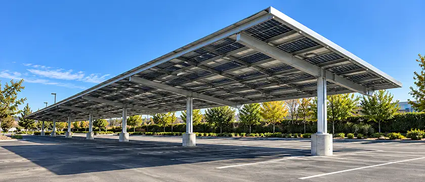
The workable column positions usually decide which of the three common frame types fits. A single-column cantilever has one column per frame, with the columns in a single row and the canopy projecting to one side. A center-post (T-shaped) frame carries the canopy on both sides of a central column row. In a dual-column frame, the main beam spans between two column rows.
A cantilever keeps the outer edge of a parking bay free of columns, but lengthening it raises the bending moment at the support and the forces passed into the column and foundation. Adding supports shortens spans and reduces the tributary area per column, at the cost of extra foundations and less open space at grade.
On an existing lot, constraints such as storm drains, utility corridors, and no-dig zones sit below the pavement. A records review and utility locate during concept design help find them while the columns can still move.
Module Layout Sets the Canopy Footprint
The parking grid and module grid rarely line up exactly, so the two are laid out together. Module dimensions, portrait or landscape orientation, the number of module rows, and the gaps between modules define the canopy footprint above the stalls.
Clear height comes early in the layout, because the vehicles using the lot determine the minimum. In the United States, the 2010 ADA Standards require at least 98 in (2,490 mm) of vertical clearance at van-accessible parking spaces, their access aisles, and the vehicle routes that serve them. That clearance is measured to the lowest element, such as a gutter or light. Delivery vans, service trucks, and fire access routes can call for more under local rules.
Raising the canopy lengthens the columns, and on a cantilevered column the same lateral wind force then produces a larger base moment. Does the design wind pressure rise too? Not necessarily. It depends on the roof height and terrain exposure used in the wind calculation.
Design Basis and Governing Loads for Solar Carports
The design basis sets out the codes and site loads used to design your carport. It is usually agreed on at the start of the project, alongside the layout, because it determines how large the members and foundations need to be.
The values in the design basis, and the way they are combined, come from the building code in force where the carport will be built. For U.S. projects, that code sets which edition of ASCE 7 applies. The current edition, ASCE/SEI 7-22, covers loads and load combinations for wind, snow, rain, seismic effects, and atmospheric ice.
In Europe, EN 1990 sets out the basis of design and is used with the EN 1991 load parts and the material-specific Eurocodes. Each country's National Annex supplies the nationally determined values. The same layout can therefore need different member sizes in different countries.
Layout Changes and Frame Forces
Beam length, support position, canopy height, and tilt all feed into the structural model, and revising any of them changes the calculated forces. If you move a column to clear a pedestrian route, the cantilever on one side can get longer.
Under a uniform load, the moment at a cantilever support grows with the square of the projection. Stretch a 2.5 m cantilever to 3.0 m, only 20% longer, and the support moment rises by about 44% at the same load per meter.
Which Load Cases Govern the Design?
Every member or connection check has its own governing case, the load combination that gives the most demanding result.
| Load Case | What It Often Governs |
|---|---|
| Dead load with snow or downward wind pressure | Beam bending and deflection |
| Wind uplift | Module attachments, beam-to-column connections, anchors, and foundation uplift resistance |
| Lateral wind or seismic load | Frame sway and added column-base moment, on top of the moment a cantilevered frame carries from its own weight |
Uplift deserves extra attention on a PV canopy. The structure carries little weight for the area it exposes to wind, and depending on the code, the uplift combinations may credit only part of that weight as resistance.
How Loads Travel Through a Solar Carport Frame
A load path is the route a force follows through the structure. Every member and connection along it passes the force to the next. For a typical solar carport, the primary path for gravity and uplift loads is:
- PV modules
- Module clamps
- Rails or purlins
- Main beams
- Columns and bracing
- Column base connection
- Foundation
- Soil
In a single-column cantilever, the canopy and any snow on it sit off to one side of the column. That eccentric load puts a moment into the base even on a calm day. The column, base connection, and foundation carry that moment in addition to the vertical load.
Airflow over and under an open canopy can create a net upward pressure on the modules. Where a freestanding carport meets the ASCE 7 definition of an open building, the free-roof provisions combine the pressures on both surfaces of the canopy. The resulting uplift follows the same load path and pulls on every connection along it.
A connection that sits in bearing under gravity can see the load reverse under uplift. A bolted angle or bracket then pulls on its bolts, and if its leg bends and presses on the connected member beyond the bolt line, the bolt tension can rise above the uplift force itself. Engineers call this prying action, and it is one reason connections are checked for uplift as well as gravity.
Member and Connection Design for Strength and Serviceability
With the loads applied, the structural model shows how much force each beam, column, and connection carries and how far the canopy moves. Main beams are checked for bending, shear, stability, and deflection. Carport columns usually carry axial compression and bending at the same time, so they are also checked for buckling and axial-bending interaction.
Connections Need Their Own Design Checks
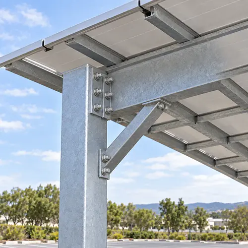
The forces in a frame concentrate at its connections, where bolts, welds, and plates transfer the load from one member to the next. Typical connection locations include:
- beam-to-column joints
- rail or purlin brackets on the main beams
- bracing connections
- beam splices, where long members are shipped in segments
- column base connections to the foundation
The design standard for these joints varies with the material and the region. In U.S. practice, ANSI/AISC 360-22 covers structural steel members and their bolted and welded connections, while thin-walled cold-formed sections such as purlins follow AISI S100. Aluminum frames follow the Aluminum Design Manual. Where anchor rods tie the frame to a concrete foundation, their anchorage is checked under ACI 318.
Strength Checks and Deflection Limits
A beam can be strong enough and still deflect too much. Strength checks ask whether members and connections can carry the design loads, while serviceability checks limit how far the structure moves under service loads.
On U.S. projects, IBC Table 1604.3 limits live-, snow-, or wind-load deflection to L/180 for roof members that do not support a ceiling. For a cantilever, L is taken as twice the projection. On a 6 m simple span, that limit allows about 33 mm at midspan. A drainage channel or module row mounted on that beam deflects with it, and a channel with a shallow slope can hold standing water even when the beam stays within that limit. Drainage requirements and module tolerances can call for a stricter project limit.
Column Reactions and Carport Foundation Design
The structural model reports the reactions at each column, and those reactions become the starting point for the foundation design. Soil conditions, existing pavement, underground services, and available excavation space then determine what kind of foundation can resist them.
Each column support can pass one or more of these forces into its foundation:
- downward vertical force
- uplift
- horizontal shear
- overturning moment
Those reactions are checked against the site's ground conditions, including bearing capacity, lateral soil resistance, uplift capacity, groundwater level, and, where it applies, the local frost depth.
Your foundation engineer needs the concurrent reactions at each column, labeled as service-level or factored, along with the base-plate, anchor rod, or embedment dimensions. Concurrent reactions are the forces that act together in one load combination. Without those labels, a reaction table is easy to misread. Soil checks and concrete anchorage design often use different load levels.
Coordinating Modules, Drainage, and Attached Equipment
Your carport frame carries the PV modules and may also support drainage components, cable routes, lighting, signage, or column-mounted EV chargers.
How Module Choice Affects the Rail and Clamp Layout
The rail and clamp layout follows the module's size, mass, orientation, and frame profile. The module you design around may not be the one you end up buying. Availability or pricing can prompt a late substitution, and a replacement with a similar power rating may still differ in length, width, mass, or clamp locations. Different dimensions change the canopy footprint and rail spacing, and new clamp locations move the support points along the module frame.
The module manufacturer's installation manual sets out the permitted mounting methods and clamp locations (often called clamping zones), and it ties each rated load to a specific mounting method.
Those ratings come from the static mechanical load test in IEC 61215-2, where the test load equals the design load multiplied by a safety factor of at least 1.5. A datasheet value such as 5400 Pa can be either the test load or the design load. If the datasheet does not say which, check with the module manufacturer.
If 5400 Pa is the front-side test load and the safety factor is the minimum 1.5, the design load is 3600 Pa (5400 / 1.5). A value already stated as a design load is not divided again. For the mounting method actually used, the downward and uplift pressures calculated at each module position are checked against the front- and rear-side design loads. Both checks use the same load basis (service or factored) as the module rating.
Drainage and Attached Equipment
Where the space under the canopy needs to stay dry, a waterproof carport collects the water that would otherwise drip through the gaps between modules. In some systems the joints are sealed, so water runs across the modules to a gutter at the low edge. In others, the joints stay open above drainage rails that carry water to the gutters and downspouts. Either way, the joint detail must preserve the module gaps and drainage openings the installation manual requires. The canopy slope and support elevations also have to keep water moving toward the discharge points.
Cable trays, conduit, lighting, signage, and junction boxes each need space and a defined attachment point on the frame. The structural team works from the weight and attachment location of each item, plus any holes needed in the members. Where the frame is part of the array's grounding or bonding path, the electrical designer specifies the bonding points and approved bonding hardware shown on the drawings. Anodized and painted surfaces are electrical insulators. Bolting two coated parts together does not by itself provide a reliable bond.
Drilling on site cuts through the zinc coating or anodized finish and leaves bare metal at the hole edge. Damaged zinc coatings can be repaired with zinc-rich paint, one of the repair methods in ASTM A780. Anodizing is a factory process, so field cuts in anodized aluminum need the touch-up method the supplier specifies.
Attachment holes shown on the fabrication drawings can be made in the factory, where the finish specification sets how their edges are treated.
From Structural Design to Fabrication-Ready Drawings
A structural calculation shows that the frame can carry its loads. Fabrication drawings then give the factory the member lengths, plates, holes, brackets, fasteners, and connection details it needs to make that frame. On steel projects, the fabrication (shop) drawings usually go to the responsible structural engineer, who reviews them against the approved design before release.
What Must Be Confirmed Before Fabrication Starts?
Anything that changes a physical part is confirmed before that part is released for fabrication. Items still open are marked as holds on the drawings, and the affected parts stay out of production until those items are settled.
| Item to Confirm | Fabrication Details Affected |
|---|---|
| Final column layout | Member lengths and connection positions |
| PV module model | Rail spacing, clamp locations, and canopy dimensions |
| Design basis and approved member design | Section sizes, plate thicknesses, and bolt groups |
| Base connection details | Base plates, anchor rod patterns, or embedment lengths |
| Drainage arrangement | Drainage rails, gutter brackets, and discharge openings |
| Attached equipment | Brackets, openings, and bonding points |
| Material and finish | Steel grade or aluminum alloy and temper, plus a coating or anodizing specification selected for the site's ISO 9223 corrosivity category and design life |
Changes after release, such as a new module, a moved column, or a revised canopy dimension, go through revision control, and the affected drawings and bill of materials (BOM) are reissued together.
BOM, Preassembly, and Installation Drawings
The BOM lists the parts and quantities shown on the fabrication drawings. Each fabricated member carries a piece mark that matches the BOM, the packing list, and the installation drawings, so crews can find the right member on site.
Some framing systems allow selected connections to be preassembled at the factory, where hole alignment and fit-up are checked before shipment. Preassembly reduces site work, and the project team weighs that against the extra container or truck space the preassembled sections take up.
Installation drawings show where each part goes and how it connects in the field, including the erection sequence and bolt tightening requirements where they apply.
Getting a Custom Solar Carport Frame for Your Project
At Mibet, we design each solar carport frame to suit its site and supply it in corrosion-protected carbon steel or anodized aluminum. Our scope covers columns, main beams, rails or purlins, connection components, base plates, clamps, and fasteners. For parking areas that need to stay dry, we also offer a waterproof carport mounting system.
Our engineering package can include structural layouts, member and connection details, column reactions and base details for your foundation designer, a bill of materials, and installation drawings. Suitable connections can also be preassembled at the factory to reduce field assembly.
To start a structural review, send us the parking layout, module datasheet, project location, required clear height, and any geotechnical data or design criteria already available.
Frequently Asked Questions
1. Is there a standard column spacing for a solar carport frame?
No single column spacing applies to every solar carport frame. The parking layout, support arrangement, beam span, design loads, foundation locations, and required clearances all affect it.
Across a large lot, a repeated grid keeps member lengths and connections consistent. The spacing is often a multiple of the stall width, so each column lines up with a stall line. The engineer then checks it against the structural model and the available support locations.
2. Does changing the PV module require the frame to be redesigned?
Not always. The project engineer first checks the new module's dimensions, mass, orientation, frame profile, clamp locations, and front- and rear-side design loads against the approved design. If the new module falls within those limits, the frame members can usually stay as designed.
New clamp locations or canopy dimensions trigger a review of the affected framing, details, and any parts already made. The change is then approved and recorded in a drawing revision.
Here is a list of the sources used to create this article.
- 2010 ADA Standards for Accessible Design, Section 502.5.
- ASCE/SEI 7-22, Minimum Design Loads and Associated Criteria for Buildings and Other Structures.
- EN 1990, Eurocode: Basis of structural design.
- EN 1991, Eurocode 1: Actions on structures.
- ANSI/AISC 360-22, Specification for Structural Steel Buildings.
- ANSI/SDI AISI S100-24, North American Specification for the Design of Cold-Formed Steel Structural Members.
- Aluminum Association, Aluminum Design Manual, 2020.
- ACI 318, Building Code for Structural Concrete.
- 2024 International Building Code, Table 1604.3.
- IEC 61215-2:2021, Terrestrial photovoltaic (PV) modules – Design qualification and type approval – Part 2: Test procedures.
- ASTM A780/A780M-20, Standard Practice for Repair of Damaged and Uncoated Areas of Hot-Dip Galvanized Coatings.
- ANSI/AISC 303-22, Code of Standard Practice for Steel Buildings and Bridges.
- ISO 9223:2012, Corrosion of metals and alloys — Corrosivity of atmospheres — Classification, determination and estimation.

Tao Chen
Marketing Director & IT Director · MIBET ENERGY
MIBET is a global designer and manufacturer of solar mounting systems. With over 10 years of professional experience, Tao Chen regularly contributes articles to our blog on structural design, installation, and maintenance, offering valuable guidance for navigating the complexities of solar projects.