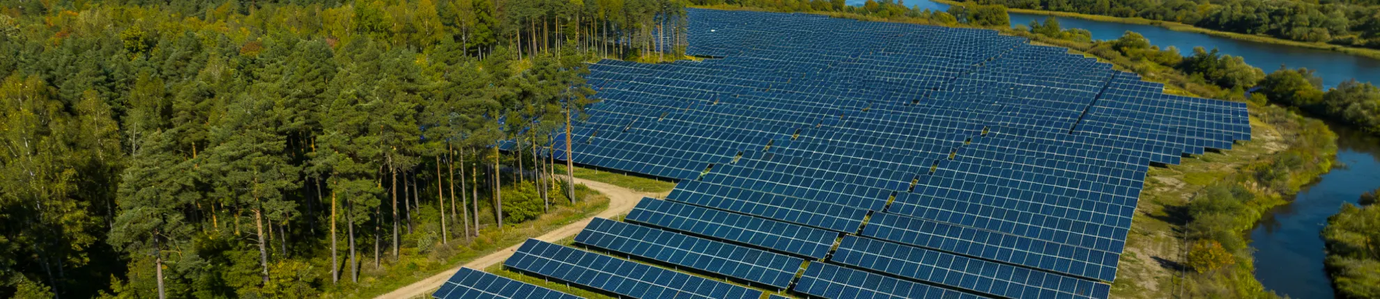
Fishery Solar Mounting System for Aquaculture Ponds
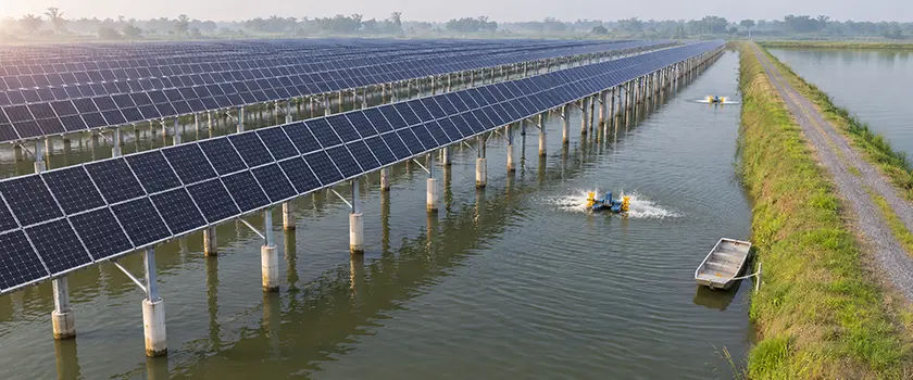
Over a working aquaculture pond, water levels and farm work set the limits on the structure, and the module layout has to fit within them. The pond bed is usually saturated silt, the waterline rises after heavy rain, and boats and harvest nets often need room to pass under the array. Once the piles go in, their positions and spacing are fixed for the life of the plant.
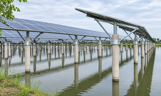
A fishery solar mounting system for aquaculture ponds is an elevated, pile-supported structure that holds photovoltaic (PV) modules above the water while farming continues below. The structure typically uses prestressed concrete piles to carry a steel frame, rails and module clamps. Bed soil and wind exposure shape the pile layout, while salinity and coastal exposure set the level of corrosion protection. The array has to sit high enough to give boats and nets working room above the highest farming water level and to keep a freeboard margin above the design flood level.
Table of Contents
- What Is a Fishery Solar Mounting System?
- Parts of a Fishery PV Mounting Structure
- How Pile-Mounted, Floating and Cable-Supported Systems Compare
- Clearance Height and Row Spacing Over the Pond
- Pile Foundations for Soft Pond Beds
- Corrosion Protection at Inland and Coastal Ponds
- Wind, Storm and Flood Loads on Open Water
- Fishery Solar Mounting Systems From Mibet
- Frequently Asked Questions
What Is a Fishery Solar Mounting System?
A fishery solar mounting system is a pile-supported PV structure built over a working aquaculture pond. On land, a ground-mount array stands on ground that rigs and trucks can drive on. Over a pond, the piles usually go into soft, saturated silt, and the waterline around them rises and falls with rain, drainage and harvest cycles. The steel frame sits in constant humidity above a splash zone at the waterline. Below the modules, the farm needs room for boats, feeders, aerators and harvest nets.
Fishery PV and fishery-solar hybrid describe the same project type, common in China and parts of Southeast Asia on freshwater fish and crab ponds, brackish shrimp ponds and coastal aquaculture ponds. Researchers use the broader term aquavoltaics, which also covers floating arrays. The appeal is dual use. One pond produces both fish and electricity, and in hot months the shade from the modules can also lower water temperature and evaporation.
Parts of a Fishery PV Mounting Structure
In a fishery PV mounting structure, loads pass from the modules through the clamps, rails and beams to the piles and into the pond bed.
| Component | Typical material | Pond-site notes |
|---|---|---|
| Mid and end clamps | Aluminum alloy with stainless steel bolts | Clamps on exposed edge rows usually carry the highest loads |
| Rails or purlins | Anodized aluminum such as 6005-T5, or cold-formed steel C or Z purlins | Fewer piles in the water usually mean wider frame spacing and longer rail spans |
| Main beams, bracing and any steel columns | Galvanized or zinc-aluminum-magnesium (ZM) coated steel | Open-water wind raises the loads on braces and connections |
| Pile-top connection | Bolt-on steel collar or embedded steel connection | Joins the steel frame to the concrete pile and carries wind and vertical loads |
| Pile or pile-column | Prestressed high-strength concrete (PHC) pipe pile | Carries a steel column at the pile top, or extends above the water as the column itself |
The pile then passes those loads into the soil. Skin friction, the grip between the pile surface and the surrounding soil, works with end bearing at the tip to support downward loads. The same friction, helped by the pile's weight, resists wind uplift, and the soil pressing against the pile takes lateral loads.
Frame layout sets how many piles go into the pond. Single-post frames keep the pile count low and leave wider gaps between piles, although each pile carries a larger bending moment. Two-post frames spread the load over more piles. Stretch the spans to widen boat lanes and you cut the pile count, but the beams get heavier. With the same load per meter, doubling a beam's span roughly quadruples its bending moment and increases its deflection about sixteenfold.
How Pile-Mounted, Floating and Cable-Supported Systems Compare
Rigid pile-mounted frames suit shallow ponds whose beds can take driven piles, and they hold modules at fixed tilt or on single-axis trackers. Floating PV handles deeper water and large water-level swings, because its pontoons rise and fall with the water while moorings tied to the bed or banks hold them in place. Cable-supported systems, often called flexible mounting, are used where a site needs long spans, and they usually stand on piles too. They carry modules on prestressed steel cables strung between widely spaced supports. Fewer supports stand in the water, but cable tension, anchor loads and vibration need close checking.
| Site condition | Rigid pile-mounted | Floating PV | Cable-supported |
|---|---|---|---|
| Water depth | Shallow ponds, including ponds drained for harvest or cleaning | Deeper water where piling becomes costly | Shallow to moderate depth |
| Water-level change | Fixed height, set above the design water levels | Floats rise and fall with the water, and moorings allow for the full range | Fixed height, set above the design water levels |
| Space for farming below | Open water between piles | Water surface under the floats is covered | Wide open areas between supports |
Pond depth, bed soil strength and storm exposure decide which structures are practical. The drainage cycle and how much open water the farm needs under the array then narrow the choice.
Clearance Height and Row Spacing Over the Pond
Why not just set the array high and leave plenty of margin? Because every added meter of clearance lengthens the supports, raises the overturning moment where each pile enters the bed and adds material to every frame. The practical aim is the lowest clearance that keeps the array above floodwater and still leaves the farm room to work.
How High Should Modules Sit Above the Water?
The lowest point of the array has to clear the highest farming water level by the headroom that boats and nets need, and the design flood level by a freeboard margin. The farming level comes from the farm's operating plan, and the flood level from a hydrological study of the site.
Freeboard keeps modules and connections clear of wind-driven waves, floodwater and floating debris. Both clearances are measured to the lowest member, which is sometimes a beam or brace below the module edge rather than the module itself. Whichever needs the higher elevation governs.
- Lowest member
- A Headroom for boats and nets
- B Freeboard
Clearance set from a dry-season survey can fall short in the wet season, when workboats lose headroom and nets start catching on low beams and braces. Ponds harvested from the banks or by draining can often work with modest headroom. Farms that run workboats under the array need enough room for the boat, its crew and any nets or gear on board.
How Pile and Row Spacing Affect Light and Access
Over a pond, row spacing limits winter shading between rows, controls how much light reaches the water and sets the width of the lanes that boats and nets use. Along each row, the distance between piles depends on how far the rails or purlins can span and how much load each pile can take. A workable layout also keeps harvest zones and fish channels clear of piles, spaces supports to suit the farm's nets and leaves room around feeders and aerators.
For a sense of scale, a 2024 study published in Water examined a 20 MW plant in Fujian, China, built over coastal mud crab ponds 0.4 to 1.4 m deep. It reports piles at 5.0 m (16.4 ft) centers and rows 7.8 m (25.6 ft) apart. Module centers sat 2.35 to 3.02 m (7.7 to 9.9 ft) above the water. The clearance under the beams and braces was lower. Those figures describe a single site with 80% PV coverage.
Pile Foundations for Soft Pond Beds
Most pond beds have soft, saturated silt over firmer clay, sand or weathered rock, and the depth of that firmer layer largely decides pile length. As with pile foundations on land, the piles pass through the silt and develop most of their capacity in the firmer layers below. Water depth and the height of the pile top set the free length of pile above the bed. A longer free length increases the bending moment where the pile enters the soil. Before production piling starts, the foundation designer usually calls for load tests on a few piles to confirm compression, uplift and lateral capacity in the actual soil.
Why Pond Projects Use PHC Pipe Piles
PHC pipe piles are hollow, prestressed concrete piles spun-cast in a factory. For pond work they offer consistent quality, durability in permanently wet ground and a unit cost that suits projects needing thousands of piles. Often the pile also rises above the water and doubles as the column.
At the top of the PHC pile, a bolt-on steel collar clamps the steel column or frame to the pile and transfers wind and vertical loads with no field welding. Welding the frame to a steel plate at the pile top would burn off the zinc coating around the weld, and the damaged area is hard to reach for repair once the pond is back in production.
Installing Piles in Drained or Flooded Ponds
Piling in a drained pond is common on working farms. Land-based rigs work from mats or temporary platforms between production cycles, and a late start can push piling into the next farming season. If your ponds cannot be drained, or draining would take them out of production for too long, piles go in from pontoons, barges or the nearby banks. Floating equipment costs more, and platform movement makes it harder to hold each pile in position and plumb.
Corrosion Protection at Inland and Coastal Ponds
One fishery structure faces three corrosion environments at once. The pile shaft stays submerged or buried, and limited oxygen there slows corrosion. The upper frame is exposed to humid air. Between the two lies the splash zone at the waterline, where daily wetting and drying with plenty of oxygen breaks down coatings fastest. On a concrete pile that rises through the waterline, the splash zone falls on the concrete, and the coated steel begins at the pile top.
Zinc protects galvanized steel by corroding first, and chlorides from brackish pond water or sea spray speed up that loss. ISO 9223 grades how corrosive a site's atmosphere is, from C1 (very low) to CX (extreme). The categories below are typical starting points, and a site assessment sets the actual category.
| Pond environment | Atmospheric category | Typical protection |
|---|---|---|
| Inland freshwater pond | Often C3 | Galvanized steel, aluminum rails, stainless steel fasteners |
| Brackish shrimp pond near the coast | Often C4, sometimes C5 | Heavier zinc or zinc-aluminum-magnesium (ZM) coatings, isolation between dissimilar metals |
| Coastal or tidal-flat pond | C5, or CX in severe marine exposure | Coating system and stainless steel grade selected for C5 or CX, with a planned inspection routine |
Zinc wears away faster with each step up in category. For an 85 µm hot-dip galvanized coating on heavy steel sections exposed to the air, ISO 14713-1 estimates the time to first maintenance at 40 to more than 100 years in C3, 20 to 40 years in C4 and 10 to 20 years in C5. A collar or brace set low enough to catch wave spray will lose zinc faster. Near the coast, a coating that would need no maintenance over 25 years inland may need to be thicker or paired with a paint system.
On galvanized steel, corrosion usually starts where water collects on the lower frame members and connections. White zinc corrosion products appear first, and red-brown rust follows once the zinc is used up. Good detailing slows that process: joints kept above the splash zone, drain holes added to hollow sections before galvanizing, and zinc-rich paint on field cuts or drilled holes. Repairs near the waterline mean working from a boat or draining the pond.
Wind, Storm and Flood Loads on Open Water
Wind usually governs the structural design of a fishery array. Open water has almost no surface roughness to slow the air, so wind at module height blows harder over a pond than over farmland lined with hedges and buildings.
Fishery PV has no dedicated international structural code. Engineers apply general wind codes, using the site's wind speeds and surrounding terrain. Large multi-pond sites often fall into each code's open-water category.
| Region and standard | How open water is classified |
|---|---|
| United States ASCE/SEI 7-22 | Exposure D where water surfaces extend upwind more than 1,524 m (5,000 ft) or 20 times the structure height, whichever is greater |
| Europe EN 1991-1-4 | Terrain category 0 (sea or coast exposed to open sea) or I (lakes and flat land without obstacles), subject to the National Annex |
| Australia and New Zealand AS/NZS 1170.2:2021 | Terrain Category 1, which the 2021 edition extends to all water surfaces |
Rows at the edges and corners of an array see higher pressure coefficients than interior rows. The structural engineer checks those frames and their clamp positions separately. On sites exposed to typhoons, hurricanes or cyclones, repeated gusts also put a cyclic load on the connections.
Over time, that cyclic loading can reduce bolt tension, which is why lock nuts or serrated flange nuts and torque checks after severe storms are common practice. Once preload is lost, the clamp grips the module frame less firmly, and the module can shift, rattle and flex in gusts. Repeated flexing may cause cell microcracks too fine to see.
The piles are checked against the design flood level as well as the farming water levels, since floodwater can push floating debris against them. In cold climates, piles are also sized for the sideways push of expanding ice and for ice that freezes to the pile and pulls upward as the water rises.
Fishery Solar Mounting Systems From Mibet
A fishery structure works best when its design starts from the pond's own water levels, bed soil, farming routine and corrosion exposure. Mibet supplies pile-mounted fishery solar mounting systems from the pile top up. The scope covers adjustable bolt-on collars that clamp the frame to each PHC pile, zinc-coated steel main beams and bracing, anodized 6005-T5 aluminum rails, mid and end clamps, and SUS304 stainless steel fasteners. Mibet's 2023 projects included a 44 MW fishery PV plant in Zhangzhou, China.
If you are planning a fishery PV project of your own, share your pond plan, water levels and any soil data with us for a preliminary layout and quotation.
Frequently Asked Questions
1. Does a fishery solar array reduce fish or shrimp yield?
A fishery solar array can affect yield, mainly because shading changes light, temperature and dissolved oxygen in the pond. In a water-quality study of a 54 MW fishery PV plant in Jiangsu, China, shading was the main factor behind changes in dissolved oxygen. How much that matters varies by farming system. The Thünen Institute ran laboratory trials modeled on Vietnamese shrimp farming. Shrimp raised in biofloc systems showed no statistically significant differences in growth or survival at light levels matching 0%, 60% and 90% PV shading. The researchers say the lab results still need confirming on working farms. Coverage ratio and row spacing control how much shade the pond receives.
2. How long does a fishery solar mounting structure last?
A fishery solar mounting structure is designed to last as long as the PV plant, typically 25 years or more. Whether it does depends largely on corrosion protection matched to the site's corrosivity category and on regular inspection of the connections closest to the splash zone.
3. Can galvanized steel affect pond water quality?
Galvanized steel can release small amounts of zinc as its coating weathers. When concrete piles hold the steel frame above the water, zinc from the frame reaches the pond mainly through rain runoff. In case studies of galvanized bridges and docks, the American Galvanizers Association, an industry body, estimated that the added zinc would stay below U.S. Clean Water Act criteria even if all of the corroded zinc reached the water. The sites studied had more water exchange than most ponds.
4. What affects the cost of a fishery solar mounting system?
The cost of a fishery solar mounting system depends on the number and length of piles, the clearance height, the frame layout and span, corrosion protection, the wind zone and the installation method. Deep silt calls for longer piles, wide boat lanes for heavier beams and coastal sites for thicker coatings. Piling from pontoons adds equipment cost.
5. Can a fishery solar mounting system handle uneven pond beds or sloped banks?
Yes. A survey of the pond bed and banks comes first. Each pile's length is then set from the bed level and soil profile at its location, so piles on a sloped bank or over a low spot differ in length. An adjustable collar at each pile top takes up the small height differences that remain and keeps the frames above in line.
6. Is a fishery solar mounting system suitable for tidal flats?
Tidal flats can host a pile-mounted fishery array, but the design has to allow for tidal range, wave and current loads, and scour around the piles. Atmospheric corrosivity at tidal-flat sites is often C5 or CX.
- The Effects of a Fishery Complementary Photovoltaic Power Plant on the Near-Surface Meteorology and Water Quality of Coastal Aquaculture Ponds, Water, 2024.
- Design and Construction of Driven Pile Foundations – Volume II, FHWA-NHI-16-010, 2016.
- ISO 9223:2012, Corrosivity of atmospheres — Classification, determination and estimation.
- ISO 14713-1:2017, Zinc coatings — Part 1: General principles of design and corrosion resistance.
- ASCE/SEI 7-22, Minimum Design Loads and Associated Criteria for Buildings and Other Structures.
- EN 1991-1-4:2005, Eurocode 1: Actions on structures - Part 1-4: General actions - Wind actions.
- AS/NZS 1170.2:2021, Structural design actions, Part 2: Wind actions.
- Differential effects of photovoltaic shading and power-frequency electromagnetic fields on water quality in aquavoltaic fish ponds, Journal of Environmental Engineering Technology, 2026.
- Dual Land Use by Aquaculture and Photovoltaics in Vietnam, Thünen Project Brief 2024/04a.
- American Galvanizers Association, Hot-Dip Galvanized Steel's Contribution to Zinc Levels in the Water Environment, 2013.

Tao Chen
Marketing Director & IT Director · MIBET ENERGY
MIBET is a global designer and manufacturer of solar mounting systems. With over 10 years of professional experience, Tao Chen regularly contributes articles to our blog on structural design, installation, and maintenance, offering valuable guidance for navigating the complexities of solar projects.