
How to Choose a Pitched Roof Solar Mounting System
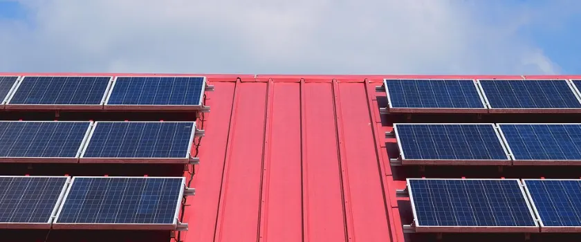
Every attachment on a pitched roof ends up passing its load into framing that was laid out long before anyone planned an array. The rafter or purlin spacing is already fixed. So is the covering, and tile, shingle and metal sheet each shed water in their own way. The framing grid and the covering narrow the choice of mounting hardware before price or brand even comes up. A hook can suit the tile profile and still miss the rafter, and a rail span that works mid-roof can fall short at the edges, where wind suction is stronger.
Choosing a pitched roof solar mounting system starts with the roof covering, which largely decides the attachment type: roof hooks for tile and slate, flashed L-feet for asphalt shingle, and hanger bolts, L-feet or seam clamps for metal roofs. The local loading code gives the wind load in each roof zone and the snow load on the roof. Those loads, the system's span tables and the rafter or purlin grid set the attachment spacing along each rail.
Table of Contents
- Pitched Roof Mounting System Types by Roof Covering
- Check Roof Framing and Pitch Before Choosing Attachments
- How Far Apart Should Roof Attachments Be?
- Weatherproofing and Corrosion Protection
- Rails, Clamps and Module Clamping Zones
- Which Certifications Apply to a Pitched Roof Mounting System?
- Get a Pitched Roof Solar Mounting Layout from Mibet
- Frequently Asked Questions
Pitched Roof Mounting System Types by Roof Covering
The attachment types differ in where they pass the array's load into the building.
| Roof covering | Attachment | Load path | Main check |
|---|---|---|---|
| Profiled clay or concrete tile (pantile, S-tile) | Roof hook passing between tile courses | Rafters, or steel battens checked for the added load | Clearance between the hook arm and the tile below |
| Flat tile and slate | Low-profile flat hook or slate hook | Rafters | Point loads on brittle tiles and slates |
| Asphalt shingle | L-foot or standoff on a flashing plate | Rafters, or the roof deck where the attachment is approved for it | Rafter location and deck condition |
| Corrugated or trapezoidal metal sheet, fiber cement | Hanger bolts with L-feet on metal or fiber cement; mini rails screwed to the crests of metal sheet | Purlins for hanger bolts, the metal sheet itself for mini rails | Purlin spacing and sheet thickness, plus an asbestos check on older fiber cement before drilling |
| Standing seam metal | Non-penetrating seam clamp on the raised seam | The seam, then the roof clips and the purlins or deck below | Clamp fit to the specific seam profile, and the capacity of the concealed clips |
A hanger bolt screws into the purlin at its lower end. Its machine-threaded upper end carries the L-foot above the sheet. On standing seam roofs, double-fold, snap-lock and bulb seams each need a matching clamp body. Concealed-fix rib profiles such as Klip-Lok take non-penetrating Klip-Lok clips shaped to fit that specific rib.
All five options are on-roof systems, with the array sitting above the existing covering. A roof facing away from the equator, or one too shallow for the modules to self-clean, can also take tilt legs or adjustable tilt brackets that lift the modules off the roof plane. With one edge raised, wind gets under the modules more freely, so uplift rises and the supports take more horizontal load.
Check Roof Framing and Pitch Before Choosing Attachments
The covering tells you which attachment type fits. The framing beneath it tells you whether that attachment can carry the load, and where it can go.
Rafters, Battens and Purlins
On wood-framed roofs, hooks and L-feet are fastened into rafters or the top chords of trusses. Tile battens are usually too small to anchor an array. Deep splits, rot or a visible sag leave a rafter with less capacity than the calculation assumes. If the covering is near the end of its service life, re-roofing before installation saves you taking the array down later.
Actual rafter positions can differ from the nominal spacing, and batten heights vary across a single roof. Tile roof hooks with slotted bases can shift sideways to land on the rafter. Height-adjustable arms bring the rails level without stacking shims under the base.
Where insulation is laid above the rafters, spacer screws or brackets bearing on the rafter carry the load through that layer without crushing it. Some systems add an angled screw for the downslope force.
On metal sheet roofs, the checks cover purlin spacing and cross-section, sheet thickness, the condition of the existing screws and whether new fasteners can reach the purlins. Sheet thickness and purlin access decide between purlin-fixed and sheet-fixed attachments.
Roof Pitch Range
Roof pitch affects which mounting systems are approved for the roof and which wind provisions apply. A mounting system's span tables and tests cover a stated pitch range, and tile roofs have a minimum pitch set by the tile manufacturer for weathertightness.
On the wind side, the ASCE 7-22 method for panels parallel to the roof applies to any roof slope. Among other limits, the panels must sit within 2° of the roof plane, no more than 10 in. (0.25 m) above it and a set distance back from roof edges and ridges. The tilted-array method covers only roofs up to 7°. Tilt legs on a steeper roof fall outside both methods, and their wind loads have to come from wind tunnel data or another accepted method.
Does a steeper roof always mean lower loads on the mounting system? Snow loads drop only above about 30°, and the force pulling down the slope keeps growing. Under EN 1991-1-3, the roof shape coefficient stays at 0.8 up to a 30° pitch and then falls linearly to zero at 60°, because snow slides off steeper slopes. With snow guards holding the snow in place, the design has to use at least 0.8 regardless of pitch.
On a 35° roof, about 57% of any vertical load acts down the slope (sin 35° ≈ 0.57), whether it comes from the array's own weight or from snow. The other component presses into the roof. The structural engineer checks attachments, rail connections and module clamps on steep roofs for that downslope pull as well as for uplift.
How Far Apart Should Roof Attachments Be?
There is no standard attachment spacing for a pitched roof solar mounting system. Spacing is worked out zone by zone from the wind and snow loads, the rail's allowable span, the capacity of each attachment and the rafter or purlin grid.
The distance between attachments along a rail is the rail span. Each attachment carries the load from its tributary area, the part of the array that extends halfway to the neighboring attachments and rails. The allowable spacing is governed by whichever link reaches its limit first: the rail in bending or deflection, the attachment itself, the fastener's withdrawal or pull-out capacity, or the rafter or purlin underneath.
Wind pressure is uneven across a pitched roof. Suction peaks along the eaves, gable edges, ridge and corners, where airflow separates from the roof surface. Attachments in those edge zones sit closer together, or the zones are left free of modules. In the US, ASCE 7 lays out the roof zones and adds a separate uplift factor for panels at exposed array edges. In Europe, EN 1991-1-4 defines the duopitch (gable) roof zones and pressure coefficients for the roof itself, and each country's National Annex can adjust them.
Where a rail runs across the rafters, attachments can only go at the crossings. Take rafters at 600 mm (about 24 in.) on center: the spacing can be 0.6, 1.2, 1.8 or 2.4 m, and with a rail that could span 2.1 m, the layout still steps down to 1.8 m. At each rail end, the overhang past the last attachment cannot exceed the cantilever limit in the system's span tables.
Weatherproofing and Corrosion Protection
A roof attachment has two jobs over the life of the array: keeping water out of the building and stopping corrosion in its metal parts and the roof metal they touch.
Flashing, Seals and Tile Clearance
A standard tile hook has to stay clear of the tile below even when snow or downward wind pressure bends its arm. The hook runs from the rafter through the joint between tile courses and turns up to carry the rail. Its arm works as a short cantilever. If the gap was set too small at installation, the arm comes to rest on the tile below. Clay and concrete tiles carry distributed loads well but crack under a point load. A hairline crack opens at the contact point and lets rain through to the underlayment.
Installation manuals set a minimum gap between the hook arm and the tile for this reason. On profiled tiles, the arm sits in the pan (the low channel of the tile below), where the overlapping tile often needs a small notch on its underside to lie flat over it. In the UK, MCS 012 turns the same principle into a certification rule. A hook for tile or slate must either transfer no load to the tiles or slates or spread its load evenly enough to pass a downward load test. For a complete system, the test load is at least 1.0 kPa (about 21 psf).
On asphalt shingle roofs, the flashing plate slides under the shingle course above the attachment, so water running down the roof passes over it. A raised seal keeps the lag screw penetration above that water path. In North America, these flashings are commonly tested to the Section 27 rain test in UL 441 or the TAS 100(A) wind-driven rain protocol. UL 2703A covers flashing devices made for PV attachments.
Fasteners on corrugated and trapezoidal sheets go through the crests, keeping each penetration above the channels that carry water. A steel-backed EPDM washer seals each fastener. Overtightening squeezes the washer out past the edge of its backing, and a loose screw leaves a visible gap against the sheet. Either way, the seal wears out sooner or lets water past.
Materials for Inland and Coastal Roofs
Pitched roof mounting systems use three main groups of materials:
- Aluminum: typically 6005-T5 extrusions for rails, clamps and hook bases, often anodized for added surface protection.
- Stainless steel: 300-series hooks and fasteners. Type 304 suits most inland sites. Type 316, which contains molybdenum, is the usual choice near the coast, where airborne chlorides are higher.
- Coated steel: hot-dip galvanized or zinc-aluminum-magnesium coated hooks and rails where extra stiffness is needed. The coating follows the site's corrosivity category under ISO 9223.
Galvanic corrosion needs two dissimilar metals in contact and moisture to act as the electrolyte. An EPDM pad under an aluminum foot or mini rail keeps the aluminum off the coated steel sheet. Stainless fasteners in aluminum rails and clamps are a standard pairing: the large area of aluminum around each small fastener keeps galvanic attack minor, except on severe coastal sites.
Rails, Clamps and Module Clamping Zones
A rail's cross-section sets its allowable span under a given load. Span tables list that span by rail profile and roof zone. Rail-less systems clamp the module frames directly to the attachments, and short-rail systems add a short rail piece at each support. With no long rails on the roof, each attachment position depends on both the module size and the rafter grid.
Mid and end clamps are sized to the module frame height, which is 30 or 35 mm on many current modules. Each clamp has to sit inside the module's clamping zones, the frame sections where the manufacturer's installation manual permits clamping. Clamp outside them and the module's rated load no longer applies.
- Clamping zone
- Clamp
- Rail
The rated load can change sharply from one clamping option to another. In Trina Solar's Vertex series user manual, the DEG18MC.20(II) module is listed at 5,400 Pa downforce and 2,400 Pa uplift when clamped on its long sides. That rating assumes clamp centerlines 350–450 mm from the frame ends and rails running across the long sides. With short-side clamping, the rating falls to 1,300 Pa and 1,000 Pa. The manual states that these are test loads and that the design load is the test load divided by a safety factor of 1.5. For example, a design snow load of 1.0 kPa (about 21 psf) on the modules already exceeds the roughly 870 Pa that short-side clamping allows for this module.
Portrait modules usually sit on two rails running across the rafters. Landscape does not have to mean short-side clamping. The same Trina module can still be clamped on its long sides with the rails running parallel to them, but its downforce rating drops to 3,600 Pa. If your project needs the 5,400 Pa rating, the rails run down the slope, either straight across the purlins or on a lower layer of rails fixed across the rafters.
Which Certifications Apply to a Pitched Roof Mounting System?
The certifications your project needs depend on the market. North American projects typically rely on a UL 2703 listing, UK projects on MCS 012 and EU projects on CE marking to EN 1090-1. Projects in all three markets still need attachment test data, evidence that any roof penetrations stay watertight and a structural calculation to the local loading code.
| Evidence | Where it applies | What it establishes | What it does not cover |
|---|---|---|---|
| UL 2703 listing | North America | Mechanical loading, bonding or fire classification of the racking with listed modules, per the listing | Roof attachments, flashing and project-specific loads |
| MCS 012 certificate (Issue 3.0) | United Kingdom | Wind uplift resistance, declared after applying a partial safety factor, and weathertightness under simulated rain | Site wind loads, which the installer checks against the declared value |
| CE marking to EN 1090-1 | European Union | Conformity of load-bearing steel and aluminum components with their declared performance | Site-specific structural design |
| Attachment load tests | All markets | Pull-out, slip and lateral capacity in a defined substrate, such as a lumber grade, purlin thickness or seam profile | Roof zones and spacing |
| Structural calculation | All markets | Design wind loads by roof zone, snow loads, attachment spacing and rail span | Product conformity, covered by certificates and attachment tests |
An attachment test covers one connection in one substrate, and a product's wind rating says nothing about the roof's height, exposure or zones. Only the project calculation brings in those site conditions.
Get a Pitched Roof Solar Mounting Layout from Mibet
Mibet manufactures pitched roof mounting systems for tile, slate and metal roofs. Its engineering team calculates attachment spacing for each roof zone from the project's wind and snow data and the measured rafter or purlin grid.
To start a layout, send our team the project location, building height, roof pitch and photos of the roof covering. Add the rafter or purlin spacing and cross-section, the module datasheet and the planned array size and orientation. You receive a layout with attachment positions marked by roof zone, a bill of materials and a budget quote. See the full range of pitched roof solar mounting systems.
Frequently Asked Questions
1. Is on-roof or in-roof mounting better for a pitched roof?
On-roof mounting suits most existing roofs, while in-roof mounting fits new builds and full roof replacements. An on-roof array sits above the covering. The roof stays in place, and the array can come off later with only local repairs at the attachment points. An in-roof array replaces a section of tiles or slates with modules and flashing trays, which gives a flush finish. A flashing kit is made for particular tile or slate profiles and batten layouts. With less air moving behind them, in-roof modules also run warmer.
2. Can a pitched roof solar mount be fixed into the roof deck instead of the rafters?
Some attachments are designed and tested for fastening into plywood or oriented strand board (OSB) roof deck, but acceptance varies by jurisdiction. For example, Palm Beach County's Building Code Advisory Board in Florida stated in a 2023 advisory that only attachments into trusses or rafters had been validated against the county's design wind loads. A deck-mounted attachment usually carries less load than a rafter-mounted one, so a deck-mounted layout needs more attachment points.
3. Can one rail and clamp set be used on tile, shingle and metal roofs?
Yes. In most rail-based systems the rails and module clamps stay the same, and only the roof attachment changes. The attachment's top connection needs to match the rail channel, commonly through an M8 or M10 T-bolt. Spacing is recalculated for each roof because a hanger bolt in a steel purlin and a hook in a wood rafter have different capacities.
Sources used for this article are listed below.
- ASCE/SEI 7-22, Minimum Design Loads and Associated Criteria for Buildings and Other Structures.
- EN 1991-1-3:2003, Eurocode 1: Actions on structures - Part 1-3: General actions - Snow loads.
- MCS 012 Issue 3.0, The Solar Mounting Standard (Product).
- UL 2703A, Outline of Investigation for Flashing Devices and Systems for Rooftop-Mounted Photovoltaics.
- BRANZ, Compatibility of aluminium and steel, 2020.
- Trina Solar User Manual Vertex Series Modules, UM-M-0002/Ver. L.
- UL 2703, Mounting Systems, Mounting Devices, Clamping/Retention Devices, and Ground Lugs for Use with Flat-Plate Photovoltaic Modules and Panels.
- Palm Beach County BCAB Technical Advisory, Rooftop Solar PV Mounting Structural Attachments (Rafter/Truss vs Wood Deck), 2023.

Tao Chen
Marketing Director & IT Director · MIBET ENERGY
MIBET is a global designer and manufacturer of solar mounting systems. With over 10 years of professional experience, Tao Chen regularly contributes articles to our blog on structural design, installation, and maintenance, offering valuable guidance for navigating the complexities of solar projects.