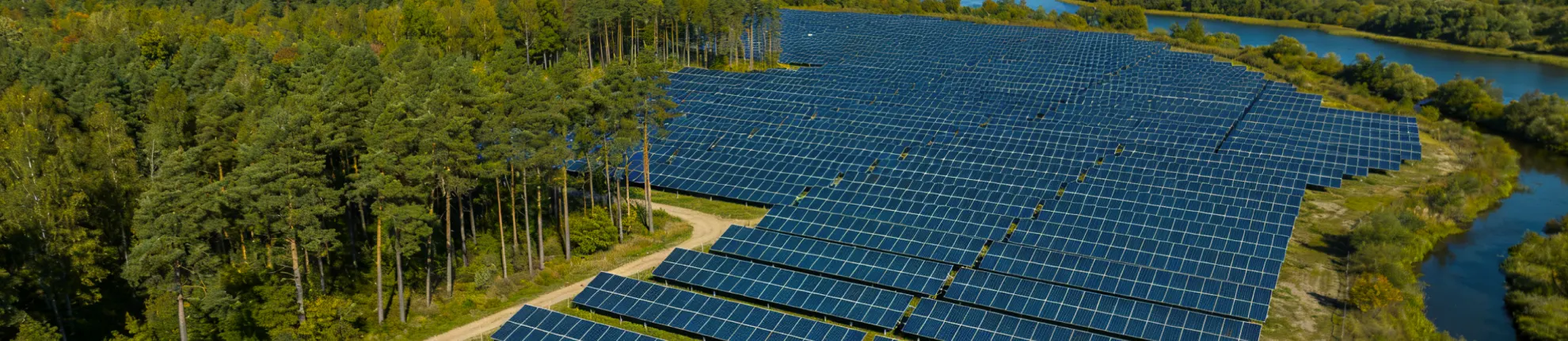
Agrivoltaic Mounting Structures: Elevated, Vertical and Inter-Row
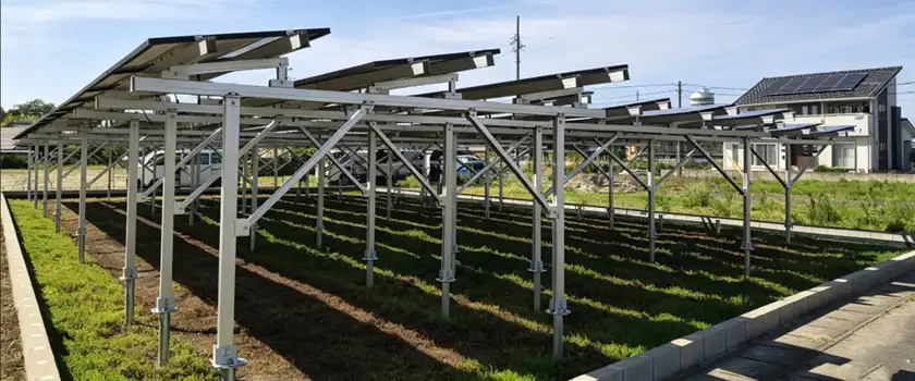
On an Agri-PV site, the farming plan shapes the structure before the module layout does. Where tractors pass, where crops grow and where animals graze set the clearance, the column grid and the row spacing. Those choices then carry through to material tonnage, foundation loads, light on the ground and energy yield.
Agrivoltaic mounting structures are commonly grouped into three types. Elevated structures lift modules high enough for crops to grow and machinery to work underneath. Germany's DIN SPEC 91434 sets a minimum clear height of 2.1 m (about 7 ft) for this overhead category. Vertical bifacial structures hold modules upright with their faces turned east and west, and inter-row structures use fixed-tilt or single-axis tracking rows. Both leave the gaps between rows for cultivation. Machinery size, crop light needs and livestock narrow the choice, and exact clearance and spacing limits depend on the site and local rules.
Table of Contents
- How Agrivoltaic Structures Are Classified
- Elevated (Overhead) Structures
- Vertical Bifacial Structures
- Inter-Row Tilted and Tracking Structures
- Elevated vs. Vertical vs. Inter-Row Structures
- Setting Clearance Height and Row Spacing
- Loads and Foundations on Working Farmland
- Elevated and Inter-Row Structures from Mibet
- Frequently Asked Questions
How Agrivoltaic Structures Are Classified
The main classification question is whether farming happens underneath the modules or between the rows. Germany's DIN SPEC 91434 uses that split. Category I covers elevated systems with enough clear height for crops to grow under the array, and Category II covers systems close to the ground, with cultivation mainly between the rows.
Italy's 2022 agrivoltaic guidelines keep that split but name three types. Raised systems allow farming under and between the modules. Inter-row systems confine it to the gaps between rows, and vertical systems stand the modules upright between crop strips. The German pre-standard places vertical arrays in Category II. Even so, their fence-like shape and east-west orientation change how they carry wind load, what foundations they need and how they generate power.
Compared with a standard ground mount on agricultural land, an agrivoltaic structure starts from a different design brief. A conventional array is laid out for energy yield and cost per watt, with modules close to the ground and rows as tight as shading allows. Here, the farm sets the clearance, column grid and row spacing first: the height of the tallest machine, the width of a spraying pass, the light a crop needs and the height grazing animals can reach. Meeting those dimensions usually means more material per kilowatt and larger foundation loads than a ground mount of the same capacity. Conventional ground mounts, along with roof and floating systems, are compared in a separate guide to the types of solar mounting structures.
Elevated (Overhead) Structures
An elevated agrivoltaic structure works like an open canopy over the field. Tall columns carry main beams that span the working lanes, and the modules sit on purlins or rails high enough for a tractor, a picking platform or a sprayer to pass underneath. The load path runs from the modules down through four groups of members:
- Purlins or module rails carry the modules and fix their spacing.
- Main beams span between columns and define the width of the clear working lanes. Their slope usually sets the module tilt.
- Columns carry vertical loads into the foundations and resist the bending that wind produces on a tall frame.
- Bracing ties the frame together to limit sway and racking in a crosswind.
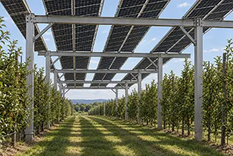
Besides clearance height, the column grid and light transmission shape the rest of the layout. In an orchard, for example, column lines can follow every second or third tree row and stay out of the drive alleys. More light on the crop always costs some capacity per hectare, whether it comes from wider gaps between modules, a lower ground coverage ratio (module area relative to land area) or semi-transparent modules.
Many early trade-offs come down to the column grid. Longer spans leave fewer columns in the field and make harvest runs simpler, but they need deeper or stiffer beams to limit deflection and keep the modules aligned. Shorter spans allow lighter members at the price of more foundations and obstacles. Aluminum is roughly one-third as stiff as steel, so a long aluminum span needs deeper sections. In return, an aluminum frame is lighter and protected by its natural oxide layer.
The usual candidates for an elevated frame are orchards, vineyards, berry crops, vegetables and other crops that benefit from partial shade or hail cover. If your orchard needs hail nets or rain covers, the PV frame can carry them as well. Their wind and hail loads go into the structural design from the start. Installation, cleaning and module replacement all happen at height. The layout has to leave room for lift access and keep cable trays above machine height.
Vertical Bifacial Structures
In a vertical bifacial array, the modules stand upright, typically in rows running north-south so that one face points east and the other west. The arrangement only works with bifacial modules, which produce power from both faces. The east face takes direct sun in the morning and the west face in the afternoon, but around noon sunlight runs almost parallel to both faces and leaves them with mostly diffuse and ground-reflected light. On clear days, the daily output curve shows a morning peak and a late-afternoon peak, with a dip around midday. The yield gap between vertical and tilted arrays narrows at high latitudes, where the sun stays low for much of the year.
A single line of posts carries horizontal rails, and the modules mount vertically on those rails. Arable farming, haymaking and grazing fit this layout well, especially on farms that run wide equipment along long, uninterrupted lanes.
Setting the lower module edge above mowing height and planting crops back from the row keeps the bottom cells clear. If the edge sits too low, a cereal crop or weeds can grow tall enough to shade the bottom row of cells late in the season. The shaded cells can switch on the bypass diode for their substring, and that substring drops out until the shade clears. With standard modules in portrait, the bottom row holds cells from every substring. A full-cell module can then lose most of its output, while a half-cut module generally loses less.
Row spacing decides how much light the crop gets. A University of Turku analysis modeled vertical rows in Finland at about 60°N. With rows 10 m (about 33 ft) apart, about 90% of the field stayed open for cultivation. Crops between the rows received roughly 80% of the irradiance of an unshaded reference.
Inter-Row Tilted and Tracking Structures
Inter-row agrivoltaic structures keep the tilted rows of a standard ground mount and change mainly their height and spacing. Cultivation needs wider gaps between rows, and grazing calls for a lower edge high enough for sheep to move beneath the modules.
Two forms are in common use:
- Raised fixed-tilt structures. Rows face the equator at a fixed angle. On two-post frames, raising the lower edge lengthens both front and rear columns, and the taller rear column usually needs diagonal bracing to keep the frame stiff. A steeper tilt lifts the upper edge further and lengthens the lever arm for wind loads. Designers treat tilt, lower-edge height and bracing as one decision.
- Single-axis trackers. Rows run north-south and track the sun from east to west, as a conventional single-axis tracker does, but stand higher and farther apart. Depending on its rotation range and controls, a tracker can hold the modules at a steep angle during field work to widen the clear lane for machinery. In that position, the lower edge drops closer to the ground.
Most structural components, from posts and rails to clamps and fasteners, carry over from standard fixed-tilt and tracker designs. Longer columns and extra bracing raise the structural cost. Wider spacing adds cable length and land area per megawatt.
Elevated vs. Vertical vs. Inter-Row Structures
Elevated structures keep almost the whole field workable under the modules and use the most material. Vertical rows give up only a narrow strip each and leave wide lanes for large machinery, while inter-row structures stay closest to standard ground-mount practice. None of the three leads on every measure, and your farming system and project location decide which trade-off pays off.
The table below compares the three agrivoltaic mounting structures on farm access, crop light and structural demands.
| Attribute | Elevated (overhead) | Vertical bifacial | Inter-row (fixed or tracking) |
|---|---|---|---|
| Where farming happens | Under the modules | Between upright rows | Between rows, grazing also beneath |
| Structure height | Tallest, machinery passes underneath | Upright rows, no members overhead | Moderate, raised lower edge |
| Light on the ground | Moving shade patches, set by module gaps and coverage | Fairly even across wide gaps | Moving bands under fixed tilt, more even under tracking |
| Typical material per kilowatt | Highest | Low to moderate | Moderate |
| Main wind effect | Overturning at column bases | Post bending from wind on either face | Uplift as on ground mounts; torsion on trackers |
| Typical farm uses | Orchards, vineyards, berries, vegetables, hail-prone crops | Arable crops, grassland, hay, grazing | Row crops, forage, hay, sheep grazing |
Material per kilowatt is a good first guide to the structure budget. It rises with clearance, span and wind exposure, and the same factors drive foundation count and erection time. Location can also reverse the economics, as a European modeling study of crop rotations in four countries showed. Elevated systems were more profitable than vertical ones in Germany and Italy, where their higher electricity output covered the added installation cost. In Sweden and Denmark, vertical systems came out ahead. Across all the agrivoltaic systems it modeled, single-axis trackers were the most profitable.
Setting Clearance Height and Row Spacing
Clearance height starts with whatever has to fit under the frame:
- the full working height of each machine and attachment, including the cab, booms, exhaust stack and GPS antenna, plus a margin
- the lowest beam, knee brace or cable tray along each working route, measured from the highest ground beneath it
- the livestock species, with cattle needing far more headroom than sheep
- the mature height of the crop, including trellises, posts and hail nets
- a tracker's full rotation range, since the lower edge drops as the rows tilt
Once you know those dimensions, the project also has to meet any agrivoltaic or dual-use rule that applies. Each rule sets its own minimum and measurement point, and their legal weight ranges from technical guidance to binding law.
| Jurisdiction and document | Legal status | Height requirement |
|---|---|---|
| Germany DIN SPEC 91434 | Pre-standard; benchmark in German Agri-PV tenders | At least 2.1 m clear height for Category I (overhead) |
| Italy 2022 guidelines, DM 436/2023 incentive rules | Ministry guideline and incentive eligibility rules for agrivoltaico avanzato systems | At least 2.1 m for crops or mixed use; 1.3 m (about 4.3 ft) for livestock or fixed vertical modules |
| France Decree No. 2024-318 | Binding national decree | No fixed value; height and row spacing must allow normal farming, animal movement and machinery passage |
| Massachusetts SMART 3.0, 225 CMR 28.00 | State incentive regulation | Lowest panel point at least 8 ft (2.4 m) for fixed tilt; at least 10 ft (3.0 m) at horizontal for trackers, with a conditional reduction to 8 ft |
| Japan MAFF agrivoltaic guideline, 2024 | Farmland conversion permit criteria | About 2 m minimum ground clearance; vertical layouts can be exempt if farming conditions are maintained |
One tracker design can meet one height rule and miss another because the rules measure from different points. Massachusetts measures fixed-tilt arrays at the lowest panel point and trackers at their horizontal position. Italy goes the other way and measures trackers at the lower module edge with the modules at their steepest tilt. Designers check clearance at both the measurement point each rule names and the lowest obstruction on the working route.
Row spacing is set the same way, by what has to fit between the rows. For vertical and inter-row structures, the clear lane between module edges allows for the width of your widest implement plus a lateral safety margin. The row pitch of tilted rows is that lane plus the strip of ground under the modules. Each lane also needs headlands at both ends wide enough for the machine to turn. The light check that follows works best season by season. An annual average shading figure can hide a shortfall during the growth stage that sets yield.
Loads and Foundations on Working Farmland
For most agrivoltaic structures, wind governs the design, and snow can take over in heavy-snow regions.
Wind and Snow Loads
Wind acts on an elevated array high above the column bases. The overturning moment at each base grows in proportion to that height, and wind speed rises with height as well.
For an open elevated array, engineers often derive the wind force from the canopy or free-roof provisions in codes such as ASCE 7 in the United States and EN 1991-1-4 in Europe. Arrays outside those provisions need site-specific analysis. On vertical rows, each post works as a cantilever from the ground, and wind can load the full module face from either side.
Snow that sheds off modules several meters up lands in a concentrated band below the low edge. Over trellised vines or a lane used for winter pruning, the band can bend trellis wires and block access until it melts. Tilt direction and lane layout decide where that band falls.
Foundations That Leave the Soil Workable
Driven piles and ground screws are the usual foundations for agrivoltaic structures. Both need little or no concrete and can be removed at decommissioning. As on any ground mount, engineers set the embedment depth from the site loads and the geotechnical investigation, then confirm it with on-site pull-out and lateral load tests.
On cultivated land, regular tillage loosens the topsoil, which would otherwise give a pile much of its lateral resistance. The pile has to mobilize that resistance in the undisturbed soil below instead. Load tests are most representative in tilled ground. Pile heads and baseplates near working lanes need to stay clear of turning machinery. Buried cables run below the depth plows and subsoilers reach, or along strips kept out of cultivation.
Elevated and Inter-Row Structures from Mibet
Mibet manufactures agrivoltaic mounting systems in two forms: elevated long-span aluminum structures that keep machinery lanes open beneath the modules, and raised fixed-tilt structures for inter-row cultivation and grazing. Each design begins with the crop or livestock plan, implement dimensions, site loads and local clearance and coverage rules. In Japan, Mibet has supplied mounting systems for agrivoltaic sites, including a 4 MW vineyard installation in Fukushima Prefecture with modules about 2.5 m (8 ft) above ground.
Share your site location, target capacity, planned crops or livestock and machinery dimensions. We will prepare a preliminary layout showing clearance and row spacing, recommend a mounting structure and provide a quotation.
Agrivoltaic Mounting Structure FAQs
1. Can an existing ground-mounted solar farm be converted to agrivoltaic use?
Often for grazing, rarely for crops. Grazing can be added if the lower module edge already sits high enough for the animals and the fencing and cable protection are upgraded. Crops are harder to add. Conventional row spacing and module height were set for energy yield, and full-size farm implements rarely fit between the rows. A retrofit for cultivation usually means rebuilding the structure with longer columns or wider spacing, typically on new foundations sized for the larger wind moment. That brings the work close to a new installation.
2. Do agrivoltaic structures need special solar modules?
No. Standard commercial modules, including the bifacial modules now common in utility projects, work on most agrivoltaic structures. Bifacial means a module generates power from both faces, not that it lets much light through to the crop. Light reaches the crop mainly through the gaps between modules or through semi-transparent modules with wider cell spacing. Lighter modules reduce the dead load on long elevated spans and are easier to lift into place.
3. Can one agrivoltaic structure support crop rotation?
Yes, if you plan the rotation before the columns go in. Column positions, clearance and row spacing stay fixed for the life of the structure. Crops, implements and light needs change from year to year. A layout designed around the tallest crop, the widest implement and the most light-demanding crop in the planned rotation works for all of them.
Sources used for this article are listed below.
- DIN SPEC 91434:2021-05, Agri-photovoltaic systems - Requirements for primary agricultural use.
- Performance evaluation of high latitude agrivoltaic systems with vertically mounted bifacial panels, Applied Energy, 2026.
- Economic evaluation of one-axis, vertical, and elevated agrivoltaic systems across Europe: a Monte Carlo Analysis, Applied Energy, 2025.
- MiTE, Linee Guida in materia di Impianti Agrivoltaici, 2022.
- GSE, DM Agrivoltaico – Regole operative, 2024.
- Décret n° 2024-318 du 8 avril 2024 relatif au développement de l'agrivoltaïsme et aux conditions d'implantation des installations photovoltaïques sur des terrains agricoles, naturels ou forestiers.
- 225 CMR 28.00, Solar Massachusetts Renewable Target (SMART) Program 3.0.
- MAFF, 営農型太陽光発電に係る農地転用許可制度上の取扱いに関するガイドライン, 2024.
- ASCE/SEI 7-22, Minimum Design Loads and Associated Criteria for Buildings and Other Structures.
- EN 1991-1-4:2005, Eurocode 1: Actions on structures - Part 1-4: General actions - Wind actions.

Tao Chen
Marketing Director & IT Director · MIBET ENERGY
MIBET is a global designer and manufacturer of solar mounting systems. With over 10 years of professional experience, Tao Chen regularly contributes articles to our blog on structural design, installation, and maintenance, offering valuable guidance for navigating the complexities of solar projects.