
What Is a Flat Roof Solar Ballast System?
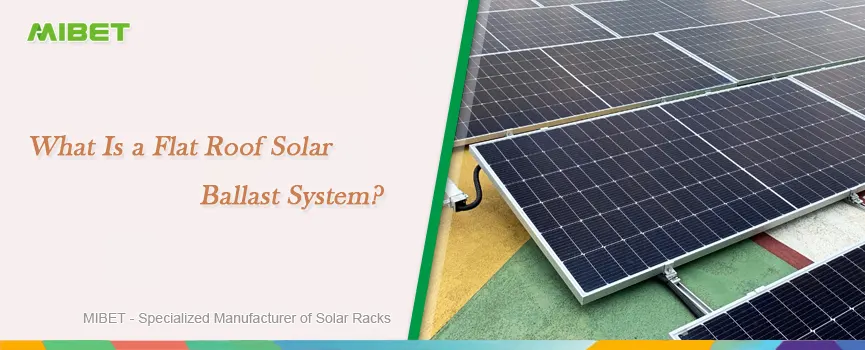
On a commercial flat roof, a mounting system that avoids structural penetrations relies on weight, friction, and the geometry of the connected racking to hold the array down. Concrete ballast is the most visible part of that system, and weight is only one input to the final layout. Site wind conditions, the roof's reserve structural capacity, the friction available at the roof interface, and the array geometry all affect how much ballast the design needs and how it is arranged. Two roofs using the same modules can still end up with different ballast quantities and support layouts.
A flat roof solar ballast system is a PV mounting system that holds the array in place with ballast, usually concrete blocks set in or on the racking, so the array resists wind uplift and sliding with few or no structural roof penetrations. Ballast quantity and placement follow from site wind conditions, building and array geometry, the array's position on the roof, the friction available at the roof interface, and any supplemental attachments. The roof structure must carry the added weight, while the roofing assembly determines the interface and protection requirements.
Table of Contents
- How Does a Flat Roof Solar Ballast System Work?
- Which Flat Roofs Are Suitable for Ballasted Solar Mounting?
- What Determines How Much Ballast a Solar Array Needs?
- What Are the Common Ballasted Solar Array Configurations?
- What Are the Advantages and Limitations of Ballasted Solar Mounting?
- What Information Is Needed to Design a Flat Roof Ballast System?
- Flat Roof Ballast System Design for Your Project
- Frequently Asked Questions
How Does a Flat Roof Solar Ballast System Work?
A fully ballasted mounting system resists uplift and sliding through ballast weight, friction at the roof interface, and the geometry of the connected racking, with no structural anchorage into the building. Hybrid layouts add selected roof attachments where the project requires them.
Main Components and Load Path
Depending on the product, the assembly includes module clamps, support frames or bases, ballast trays, ballast blocks, roof-interface pads or protection layers, inter-row connections, and wind deflectors. In a hybrid layout, selected roof attachments provide an additional load path alongside the ballasted racking. The ballast itself is usually precast concrete blocks or concrete pavers. Many projects buy them locally, so the racking bill of materials and the ballast arrive from two different suppliers, and that split affects both cost and delivery sequencing on site.
Gravity acts downward on the modules, racking, and ballast. Wind produces uplift across the module surfaces and horizontal drag across the array.
The modules and racking transfer their weight through the clamps and the support frame or base to the roof surface. Ballast is not part of that chain. Its weight is added at the base or tray, and it works against uplift and sliding rather than carrying the modules.
Racking geometry and row connections decide how the wind forces move between adjacent supports. Connected bases share load between supports as far as the racking design allows. An isolated base carries its own tributary load.
Some systems add wind deflectors to change the airflow around and under the modules. A deflector can reduce the pressure difference across the module surface, which lowers the uplift the ballast has to resist. That reduction applies only where the system's tested or calculated design basis accounts for it.
How Ballast Resists Uplift and Sliding
Ballast resists uplift and sliding at the same time. Its weight offsets the uplift trying to lift the array off the roof, and the same weight presses the mounting feet onto the roof surface.
The sliding resistance at each foot is the normal force at that contact multiplied by the friction coefficient of the two materials. That normal force is the net downward load under the governing load combination, so it counts the weight of the modules, racking, and ballast and subtracts the uplift acting at the same time.
Change the pad material and the sliding resistance changes, even though the ballast weight has not. The same pad that supplies that friction also keeps the racking off the roofing membrane.
The friction coefficient is a design input that needs verification. The Los Angeles County plan review list for PV systems, for instance, calls for a friction test report prepared to ASTM G115 at an approved laboratory to support the coefficient used in the design. The submittal should identify the pad material and the coefficient behind the calculation.
More ballast is not always the safer choice. Extra weight raises resistance to wind loads, and the same blocks become permanent dead load on a building designed long before the array existed. The mounting designer sets the quantity and its distribution, and the project's structural engineer confirms the building can carry the result.
Which Flat Roofs Are Suitable for Ballasted Solar Mounting?
Four early checks are reserve structural capacity, remaining roof service life, roof slope, and roofing-warranty requirements. A roof can be in sound condition and still lack enough reserve structural capacity for the proposed array, since the structure has to take the array and its ballast on top of the loads it was designed for.
As roof slope increases, a larger component of the array weight acts downslope and increases the demand on friction. Adopted codes may also limit the roof slope permitted for a fully ballasted array. Where the membrane is close to the end of its service life, owners normally re-cover before the array goes on.
For membrane roofs, TPO, PVC, and EPDM name only the exposed waterproofing layer. Insulation, cover board, membrane attachment method, structural deck, protection requirements, and warranty terms all change how the racking meets the roof.
Warranty terms are procedural as much as technical. Warranty programs may require pre-installation layout review, a protection course beneath the racking, membrane work by an authorized applicator, and notification after installation. Missing one of them can put coverage at risk on a roof that is otherwise sound.
The roof plan, the roof build-up, and the basic structural information you can supply at concept stage tell the mounting designer more than the membrane name alone.
What Determines How Much Ballast a Solar Array Needs?
Ballast quantity is calculated for one specific building, working from site wind conditions, building height and geometry, the array's position on the roof, module size and tilt, and the friction available at the roof interface. Greater building height, higher site exposure, or an array positioned closer to a roof edge all raise the design pressures the layout has to resist.
For U.S. projects, ASCE/SEI 7-22 Section 29.4.3 covers rooftop solar panels on flat roofs and on gable or hip roofs pitched below 7 degrees. Its tabulated pressures apply only within a defined range of panel gaps, gap spacing, tilt, panel height, and roof-edge clearance. Changes to those dimensions can require the wind calculation to be checked again. The applicable edition depends on local code adoption, and projects outside the United States work to a different structural standard.
| Design Variable | Why It Matters | Project Effect |
|---|---|---|
| Site wind conditions | Set the wind actions acting on the array | Can change ballast quantity or attachment reactions |
| Building height and geometry | Change rooftop pressure patterns and airflow | Need confirmation before final mounting design |
| Parapets and rooftop obstructions | Alter local airflow | Their effect depends on the applicable design method |
| Array position on the roof | Wind effects vary across roof and array zones | Ballast can vary within one project |
| Module dimensions | Change exposed area and support geometry | Must match the racking engineering basis |
| Module tilt and orientation | Change array aerodynamics | Affect both layout and ballast design |
| Row spacing and array geometry | Affect airflow and load sharing | Layout changes can alter ballast requirements |
| Roof interface and friction | Set the sliding resistance available at each base | Installed materials need to match the design assumptions |
| Supplemental roof attachments | Provide another load path | Can reduce dependence on ballast in a hybrid layout |
Snow and seismic enter through the load combinations as separate design actions. Snow adds gravity load to the roof and racking, and it draws on the same structural reserve the ballast needs. Seismic provisions require a different set of checks. ASCE 7 Section 13.6.12 sets conditions for arrays that remain unattached to the roof structure. If those conditions are not met, the design may require roof attachments, together with checks on displacement and panel interconnection. The adopted code and design method determine which route applies.
If your array position, module size, or tilt changes after the ballast schedule is issued, the layout has to be re-checked. Ballast quantities do not scale with module count.
Ballast Requirements Vary Across the Roof
Wind pressure is not uniform across a rooftop. Edges, corners, array perimeters, parapets, and changes in building geometry create different design conditions on the same roof. A single roof can require several ballast quantities. Procurement needs the total tonnage. Installers need the block count at each position.
The zone-by-zone ballast schedule links the structural design to the installed array. Moving blocks between zones changes that layout even when the total weight on the roof stays the same. It also records the intended ballast placement for future inspections or roof work.
Why There Is No Universal kg per Module Answer
A figure given only as kilograms of ballast per module leaves out the conditions that produced it. The same mass can belong to different module sizes, tilt angles, roof zones, friction assumptions, building heights, and wind speeds.
System configuration can also change the required ballast. Two products at the same tilt can need different quantities if one uses tested wind deflectors and the other accepts supplemental roof attachments across part of the array.
A preliminary figure can still help with early budgeting as long as its assumptions are stated. Final purchasing and installation quantities follow the project ballast layout.
What Are the Common Ballasted Solar Array Configurations?
Commercial flat-roof arrays generally use one of two layouts: a single-tilt array facing one main direction, or a dual-tilt array with opposing module orientations.
The layout affects roof utilization, row spacing, energy production, access, and wind behavior. The ballast calculation needs the final array geometry, since tilt and orientation change the shape the array presents to the wind.
Single-Tilt Arrays
A single-tilt array arranges modules in rows facing one primary direction, south in the northern hemisphere and north in the southern. Row spacing depends on module tilt, shading targets, roof geometry, and access requirements.
A higher tilt changes both the solar geometry and the wind exposure of the modules. Wider row spacing reduces row-to-row shading, and it also reduces the number of modules that fit within a given roof area.
Energy modeling and mounting design should use the same layout assumptions.
East-West Dual-Tilt Arrays
An east-west array places adjacent module planes in opposite directions. Some racking systems allow a tighter repeating layout for this arrangement, which suits projects where module density is the priority.
The opposing module planes also create a different aerodynamic geometry. Ballast quantities follow the engineering basis established for that specific mounting configuration.
| Design Consideration | Single Tilt | East-West Dual Tilt |
|---|---|---|
| Module arrangement | One primary direction | Two opposing directions |
| Row spacing | Usually includes distinct gaps between rows | Can use a more compact repeating geometry |
| Roof utilization | Depends on tilt, spacing, and setbacks | Can support higher module density with suitable racking |
Module orientation and tilt should be settled before the final ballast schedule. A late layout change alters the support arrangement, the ballast quantity, and the bill of materials.
What Are the Advantages and Limitations of Ballasted Solar Mounting?
Ballasted mounting trades roof penetrations for roof load. It keeps the racking work at the roof surface and limits structural penetrations, and it adds permanent weight the building has to absorb for the life of the array.
Fewer attachment points mean fewer flashing details to coordinate with the roofing system. Sections of the array can also be removed and reinstalled for roof work without adding new structural penetrations.
Average array load in kg/m2 (psf) is useful for early planning, but it does not show the localized reactions at individual supports. Bases and ballast blocks concentrate load at their contact areas, so local reactions can exceed the roof-wide average. Roof capacity has to be confirmed against those point loads before the mounting layout is finalized.
A flat roof leaves module orientation and row layout open, and the usable area is still smaller than the roof outline suggests. Drains, parapets, rooftop equipment, maintenance access, fire requirements, and areas where roof capacity is limited all shape the final array.
What Information Is Needed to Design a Flat Roof Ballast System?
Early design usually starts with four inputs: project location, roof plan, roof structure information, and the module datasheet. The engineering inputs need to be confirmed before the final mounting design, while the project and site information supports roof coordination and installation planning.
| Project Input | How It Is Used |
|---|---|
| Project location | Establishes environmental loads and applicable code criteria |
| Building height and dimensions | Provide geometry for wind calculations |
| Roof plan | Defines array boundaries, drains, obstructions, and usable space |
| Roof structure information | Supports review of added and localized loads |
| Roof membrane and roof assembly | Define interface and protection requirements |
| Roof interface materials | Set the friction coefficient used in the sliding calculation |
| Module datasheet | Provides dimensions, frame details, and mounting compatibility |
| Module quantity | Sets array size |
| Module orientation | Defines array geometry |
| Planned tilt | Affects layout and aerodynamic calculations |
| Structural load limits | Constrain ballast quantity and support locations |
| Rooftop equipment and drainage | Define access and exclusion areas |
| Wind, snow, seismic, and other applicable criteria | Establish the structural design basis |
| Existing roof age and remaining service life | Flag whether re-covering the roof should be considered before the array goes on |
| Roof warranty status and documentation | Set the review, protection-layer, and installer requirements that apply before work starts |
| Roof access and hoisting arrangements | Set where ballast can be landed and staged during installation |
| Local code or approval requirements | Identify the governing design and documentation requirements |
If you are working with an existing building, confirm the available structural drawings early. Missing records can delay the final roof-capacity review.
Changing the module size can alter support spacing, while a different tilt changes array geometry. Revised building dimensions or wind criteria require a corresponding check of the ballast schedule.
Flat Roof Ballast System Design for Your Project
Mibet designs project-specific flat roof solar ballast systems using confirmed module data, roof information, building geometry, structural capacity, and site load criteria. The project package can include the array layout, zone-by-zone ballast schedule, racking bill of materials, roof-interface requirements, and installation drawings, so procurement and installation teams use the same material quantities and ballast layout.
If structural capacity, wind loading, or other project requirements call for a hybrid layout, the Mibet engineering team can add selected roof attachments to the design and supply a combined ballast-and-attachment mounting option.
Frequently Asked Questions
1. Can ballasted solar mounting be used on TPO, PVC, and EPDM roofs?
Yes. Many TPO, PVC, and EPDM roof assemblies can carry a ballasted array under suitable project conditions. Compatibility depends on the full roofing assembly, structural capacity, protection or separation layer, racking interface, drainage, warranty terms, and the mounting design.
Friction performance and membrane protection are verified separately, even when one interface material serves both functions.
2. Can a ballasted solar system be installed on an existing building?
Yes, where the roof structure and roofing assembly accept the proposed loads and installation conditions. Roof condition, remaining service life, reserve structural capacity, drainage, access, and warranty terms all belong in the review before the array layout is finalized.
Any roofing-manufacturer warranty conditions apply alongside the structural and code requirements. Depending on the warranty, requirements may include pre-installation layout review, protection beneath the racking, authorized membrane work, and post-installation notification.
3. Do roof parapets reduce the amount of solar ballast required?
Not on their own. Parapets alter rooftop airflow, and the resulting effect depends on parapet geometry, building dimensions, array position, and the design method used for the project.
A tall parapet also shades the roof close to the wall. The first row of modules then sits further back, and the usable array area shrinks.
4. Can ballast be added later if the array needs more wind resistance?
Sometimes, but only after engineering review. Extra ballast changes the permanent roof load and the local reactions at the affected support points, and additional ballast may not be feasible if the roof has little reserve structural capacity.
When project wind conditions, array geometry, or mounting details change, engineers check the revised configuration before ballast quantities or locations are changed. The ballast schedule and as-built documentation are then updated to match. On a roof still under warranty, the rework follows the same requirements that governed the original installation.
5. What happens to a ballasted solar array when the roof needs replacement?
At least the affected sections of the array need to be removed. The racking, ballast, and protection layers all sit above the roofing system, so the roofing crew cannot reach the membrane until those components are moved and then returned to the approved mounting layout.
Roof age and expected service life should be considered before installation. Where the remaining roof life falls well short of the array's service life, re-covering first avoids a later removal and reinstallation cycle. Ballast blocks and racking components are generally reusable. Pads and protection layers may need replacement depending on their condition and the roofing requirements.
Here is a list of the sources used to create this article.
- ASCE/SEI 7-22, Minimum Design Loads and Associated Criteria for Buildings and Other Structures. ASCE, 2022.
- ASTM G115, Standard Guide for Measuring and Reporting Friction Coefficients. ASTM International.
- Solar PV System Plan Review List. County of Los Angeles Department of Public Works, Building and Safety Division.

Tao Chen
Marketing Director & IT Director · MIBET ENERGY
MIBET is a global designer and manufacturer of solar mounting systems. With over 10 years of professional experience, Tao Chen regularly contributes articles to our blog on structural design, installation, and maintenance, offering valuable guidance for navigating the complexities of solar projects.